Testbed water module: Difference between revisions
No edit summary |
|||
| (29 intermediate revisions by 6 users not shown) | |||
| Line 1: | Line 1: | ||
{{Water Module buttons}} | |||
__NOTOC__ | __NOTOC__ | ||
This page provides an overview and explanation about the | This page provides an overview and explanation about the Demo Water project, available for all users. | ||
===About the project=== | ===About the project=== | ||
The project '' | The project ''Demo Water'' project is available for all users and can be found in the main menu under Edit projects. This project does not count for your license. | ||
In | In this project, several components of the [[Water Module]] are visible. It can serve as a working demo to further explore the details of the available components, the used models and formulas and the configurable parameters. | ||
====Contents==== | ====Contents==== | ||
The | The ''Demo Water''project demonstrates the following components of the [[Water_Module|Water Module]]: | ||
#[[#1. Flooding related components|Flooding related components]] | #[[#1. Flooding related components|Flooding related components]] | ||
#[[#2. Rainfall related | #[[#2. Rainfall related components|Rainfall related components]] | ||
#[[#3. Hydraulic structures|Hydraulic structures]] | #[[#3. Hydraulic structures|Hydraulic structures]] | ||
#[[#4. Groundwater related components|Groundwater related components]] | #[[#4. Groundwater related components|Groundwater related components]] | ||
| Line 15: | Line 17: | ||
===1. Flooding related components=== | ===1. Flooding related components=== | ||
[[File:Flooding_testbed.JPG|thumb|right|300px|Flooding, breaches and inundation]] | [[File:Flooding_testbed.JPG|thumb|right|300px|Flooding, breaches and inundation]] | ||
This specific testbed can be found in the upper right quadrant named: ''Flooding, breaches and inundation''. This quadrant demonstrates a flooding caused by breaches in the levees and the consequential flow of several tracers in the accumulated amount of water. Two types of breaches are visualized: a breach with an [[External_area_(Water_Overlay)|external water area]] and a breach with an [[Breach_input_area_(Water_Overlay)|internal area]]. | |||
Analyse the quadrant: | Analyse the quadrant: | ||
# Click on the arrows in the quadrant to get familiar with the boundary conditions in the model. | # Click on the arrows in the quadrant to get familiar with the boundary conditions in the model. | ||
# Go to the Flooding Overlay (named ''1. Flooding'') in the Overlay bar. Play the flooding overlay. This overlay shows the [[Surface_last_value_result_type_(Water_Overlay)|Surface last value]] result type. | # Go to the Flooding Overlay (named ''1. Flooding'') in the Overlay bar. Play the flooding overlay. This overlay shows the [[Surface_last_value_result_type_(Water_Overlay)|Surface last value]] result type. | ||
# Go to the [[ | # Go to the [[Surface_last_direction_result_type_(Water_Overlay)|Direction]] result type and notice how the water surrounds the construction in the middle of the quadrant. | ||
# Take a look at the [[ | # Take a look at the [[Tracer_ABCD_(Water_Overlay)|Substance A, Substance B and Substance C]] Overlays and notice how these tracers are distributed in the water. | ||
# Go to the | # Go to the attributes tab of the Flooding Overlay and notice the value for the [[Design_flood_elevation_m_model_attribute_(Water_Overlay)|Design flood elevation]]. | ||
# Open the flooding wizard and take a look at the settings for the flood event, breach areas, inundation areas and output overlays. | # Open the flooding configuration wizard and take a look at the settings for the flood event, breach areas, inundation areas and output overlays. | ||
More information on each component: | More information on each component: | ||
| Line 29: | Line 31: | ||
*[[Breach_(Water_Overlay)| Breach]] | *[[Breach_(Water_Overlay)| Breach]] | ||
*[[Inundation_area_(Water_Overlay)|Inundated area]] | *[[Inundation_area_(Water_Overlay)|Inundated area]] | ||
*[[ | *[[Tracer_ABCD_(Water_Overlay)|Tracer Overlays]] | ||
*[[ | *[[Tracer_flow_model_(Water_Overlay)|Tracer flow model]] | ||
<br> | <br> | ||
===2. Rainfall related | ===2. Rainfall related components=== | ||
[[File:Rainfall_testbed.JPG|thumb|right|300px|Rain and sewer system]] | [[File:Rainfall_testbed.JPG|thumb|right|300px|Rain and sewer system]] | ||
For the | For the test-bed, see the quadrant named: ''Rain and sewer system''. This quadrant demonstrates flooding due to rainfall and the workings of the sewer system. | ||
Analyze the quadrant: | |||
# Click on the arrows in the quadrant to get familiar with the boundary conditions in the model. | # Click on the arrows in the quadrant to get familiar with the boundary conditions in the model. | ||
# Go to the [[Base_types_result_type_(Water_Overlay)|Base types]] result type (in the overlay ''2. Rainfall flooding'') and notice that the buildings and roads are connected to the sewer. | # Go to the [[Base_types_result_type_(Water_Overlay)|Base types]] result type (in the overlay ''2. Rainfall flooding'') and notice that the buildings and roads are connected to the sewer. | ||
# Inspect the different functions in the quadrant. | # Inspect the different functions in the quadrant. | ||
# Go to the Rainfall Flooding in the Overlay bar. Play the Rainfall flooding overlay and notice where rain puddles occur. This overlay shows the [[Surface_last_value_result_type_(Water_Overlay)|surface last value]] result type. | # Go to the Rainfall Flooding in the Overlay bar. Play the Rainfall flooding overlay and notice where rain puddles occur. This overlay shows the [[Surface_last_value_result_type_(Water_Overlay)|surface last value]] result type. | ||
# Open the Rainfall wizard and take a look at the settings for the rain event, sewer areas, sewer overflow and output overlays. | # Open the Rainfall configuration wizard and take a look at the settings for the rain event, sewer areas, sewer overflow and output overlays. | ||
More information on each component: | More information on each component: | ||
| Line 52: | Line 54: | ||
#[[Storage_model_(Water_Overlay)|Water storage]] (for example: the parking space with a crate based system) | #[[Storage_model_(Water_Overlay)|Water storage]] (for example: the parking space with a crate based system) | ||
<br> | <br> | ||
===3. Hydraulic structures=== | ===3. Hydraulic structures=== | ||
[[File:Constructions_testbed.JPG|thumb|right|300px| | [[File:Constructions_testbed.JPG|thumb|right|300px|Hydraulic Structures]] | ||
For the testbed, see the quadrant named: '' | For the testbed, see the quadrant named: ''Hydraulic Structures''. This quadrant demonstrates how several hydraulic structures work. | ||
Analyze the quadrant: | |||
# Click on the arrows in the quadrant to get familiar with which different structures are in the model and their functions. | # Click on the arrows in the quadrant to get familiar with which different structures are in the model and their functions. | ||
# Inspect the different [[Area|areas]] to see the water level in the Areas menu. The areas are in the CIRCULATING_WATER group. The water level is defined as the sloot_area attribute. | # Inspect the different [[Area|areas]] to see the water level in the Areas menu. The areas are in the CIRCULATING_WATER group. The water level is defined as the sloot_area attribute. | ||
# Go to the Hydraulic structures overlay in the Overlay bar (named: ''3. Hydraulic structures surface last value''). Play the [[ | # Go to the Hydraulic structures overlay in the Overlay bar (named: ''3. Hydraulic structures surface last value''). Play the [[Tracer_ABCD_(Water_Overlay)|Substance flow]] and notice how the water flows. | ||
# Open the wizard and take a look at the settings for the | # Open the wizard and take a look at the settings for the weirs, culverts, pump and inlets. | ||
More information on each component: | More information on each component: | ||
#[[ | #[[Weir (Water Overlay)]] | ||
#[[ | #[[Culvert (Water Overlay)]] | ||
#[[ | #[[Pump (Water Overlay)]] | ||
#[[Inlet (Water Overlay)]], which can also server as an Outlet. | |||
===4. Groundwater related components=== | ===4. Groundwater related components=== | ||
[[File:Testbed_groundwater.JPG|thumb|right|300px|Groundwater]] | [[File:Testbed_groundwater.JPG|thumb|right|300px|Groundwater]] | ||
| Line 79: | Line 83: | ||
More information on each component: | More information on each component: | ||
#[[ | #[[Groundwater (Overlay)|Groundwater Overlay]] | ||
#[[ | #[[Ground model (Water Overlay)|Ground water flow]] | ||
#[[ | #[[Infiltration model (Water Overlay)|Ground infiltration]] | ||
#[[ | #[[Evapotranspiration model (Water Overlay)|Evaporation variation over time]] | ||
#[[ | #[[Evapotranspiration model (Water Overlay)|Ground transpiration and vegetation root depths]] | ||
{{article end | |||
|seealso= | |||
* [[List of Demo Projects]] | |||
}} | |||
[[Category:Demo projects]] | |||
Latest revision as of 13:47, 16 July 2025
This page provides an overview and explanation about the Demo Water project, available for all users.
About the project
The project Demo Water project is available for all users and can be found in the main menu under Edit projects. This project does not count for your license. In this project, several components of the Water Module are visible. It can serve as a working demo to further explore the details of the available components, the used models and formulas and the configurable parameters.
Contents
The Demo Waterproject demonstrates the following components of the Water Module:
- Flooding related components
- Rainfall related components
- Hydraulic structures
- Groundwater related components
1. Flooding related components

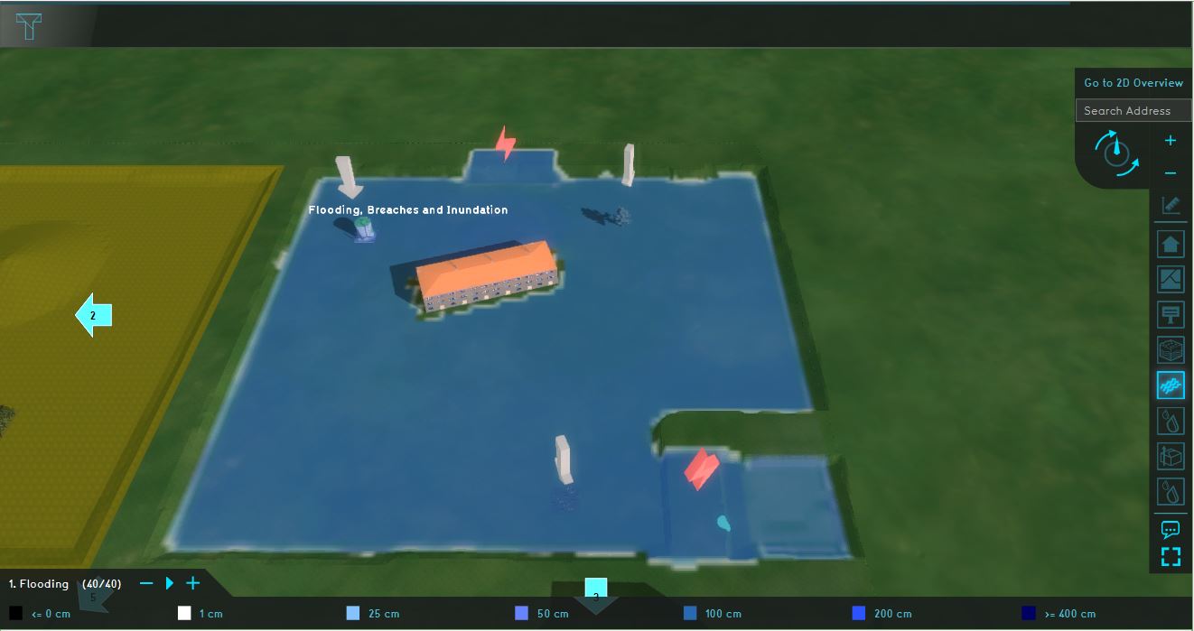
This specific testbed can be found in the upper right quadrant named: Flooding, breaches and inundation. This quadrant demonstrates a flooding caused by breaches in the levees and the consequential flow of several tracers in the accumulated amount of water. Two types of breaches are visualized: a breach with an external water area and a breach with an internal area.
Analyse the quadrant:
- Click on the arrows in the quadrant to get familiar with the boundary conditions in the model.
- Go to the Flooding Overlay (named 1. Flooding) in the Overlay bar. Play the flooding overlay. This overlay shows the Surface last value result type.
- Go to the Direction result type and notice how the water surrounds the construction in the middle of the quadrant.
- Take a look at the Substance A, Substance B and Substance C Overlays and notice how these tracers are distributed in the water.
- Go to the attributes tab of the Flooding Overlay and notice the value for the Design flood elevation.
- Open the flooding configuration wizard and take a look at the settings for the flood event, breach areas, inundation areas and output overlays.
More information on each component:
2. Rainfall related components

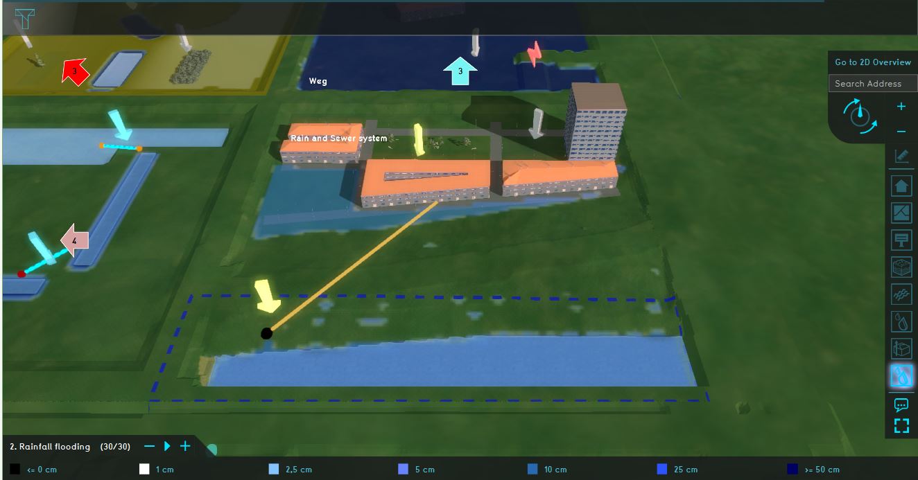
For the test-bed, see the quadrant named: Rain and sewer system. This quadrant demonstrates flooding due to rainfall and the workings of the sewer system.
Analyze the quadrant:
- Click on the arrows in the quadrant to get familiar with the boundary conditions in the model.
- Go to the Base types result type (in the overlay 2. Rainfall flooding) and notice that the buildings and roads are connected to the sewer.
- Inspect the different functions in the quadrant.
- Go to the Rainfall Flooding in the Overlay bar. Play the Rainfall flooding overlay and notice where rain puddles occur. This overlay shows the surface last value result type.
- Open the Rainfall configuration wizard and take a look at the settings for the rain event, sewer areas, sewer overflow and output overlays.
More information on each component:
- Rainfall overlay
- Rain (Weather)
- Sewer infiltration
- Sewer overflow
- Infiltration
- Water storage (for example: the parking space with a crate based system)
3. Hydraulic structures

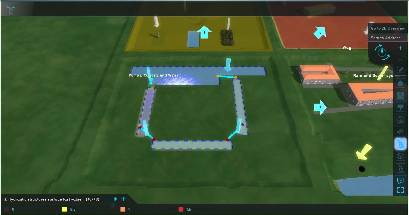
For the testbed, see the quadrant named: Hydraulic Structures. This quadrant demonstrates how several hydraulic structures work.
Analyze the quadrant:
- Click on the arrows in the quadrant to get familiar with which different structures are in the model and their functions.
- Inspect the different areas to see the water level in the Areas menu. The areas are in the CIRCULATING_WATER group. The water level is defined as the sloot_area attribute.
- Go to the Hydraulic structures overlay in the Overlay bar (named: 3. Hydraulic structures surface last value). Play the Substance flow and notice how the water flows.
- Open the wizard and take a look at the settings for the weirs, culverts, pump and inlets.
More information on each component:
- Weir (Water Overlay)
- Culvert (Water Overlay)
- Pump (Water Overlay)
- Inlet (Water Overlay), which can also server as an Outlet.
4. Groundwater related components

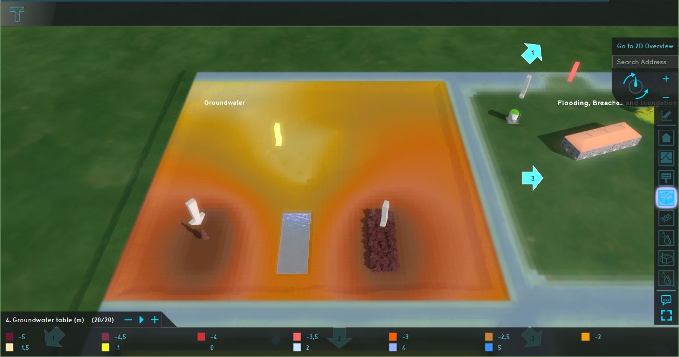
For the testbed, see the quadrant named: Groundwater. This quadrant demonstrates Groundwater flows and evaporation.
Analyse the quadrant:
- Click on the arrows in the quadrant to get familiar with the boundary conditions in the model.
- Check the Heightmap Overlay (named: Heightmap) and the Subsurface overlay (in the Overlay group 4. Groundwater table (m)).
- Inspect the depth of plant roots (m) attribute for the Nature functions in the functions values table to see how the root depth differs for the Pine trees and the Deciduous bush.
- Play the Groundwater table (m) overlay and see how the groundwater during the simulation time changes. Also inspect the Evaporation, groundwater last value and the Surface last value Overlays.
- Open the Groundwater wizard and take a look at the settings for the weather, inundation areas, functions and output overlays.
More information on each component:
- Groundwater Overlay
- Ground water flow
- Ground infiltration
- Evaporation variation over time
- Ground transpiration and vegetation root depths


