Networks tutorial: Difference between revisions
mNo edit summary |
|||
| Line 47: | Line 47: | ||
[[File:network-draw4.jpg|350px|frame|center|A relatively simple network with a few offshoots.]] | [[File:network-draw4.jpg|350px|frame|center|A relatively simple network with a few offshoots.]] | ||
This series of net lines together form a very simple network | |||
<!-- | <!-- | ||
| Line 53: | Line 54: | ||
Producer load | Producer load | ||
Consumer load | Consumer load | ||
Test run | |||
Flow variables calculated | |||
--> | --> | ||
Revision as of 11:34, 4 June 2019
Prerequisites
The following prerequisites should be met before starting this tutorial:
- This tutorial relies on base knowledge about the editor interface. If you have not yet followed the tutorials related to those subjects please do so first.
- This tutorial can be followed with any project of any arbitrary location. Recommended is to create or load a project in the editor with an urban residential area with multiple neighborhoods.
- Microsoft Excel is required for completing this tutorial.
Preparations
Take the following steps as preparation for following this tutorial:
- Start your project. This can be a pre-existing project, or a newly created project.
Introduction to networks
Networks are a separate data layer in a 3D world, intended to model actual resource transport networks, such as for gas, heat, and internet. They are modeled as a mathematical graph consisting of vertices (points) and edges (lines connecting the points).
Networks are composed of a number of datatypes:
- Net Nodes: These form the vertices of the network graph; the individual points which can be connected by lines. Net nodes cannot be directly edited as a discrete datatype as such, but are a relevant datatype to be aware of when working with networks.
- Net Lines: These form the edges of the network; the connections between the points. Net lines are defined by the net nodes they connect, and for the connections between one point on the network and another.
- Net Loads: These form a collection of properties for end-points on the network, and must be connected to any net node which forms an end-point on the network. This means that any net node which has only 1 net line connecting to it should have a net load connected to it. The net load defines the amount of the specified resource the endpoint produces or consumes.
These datatypes form the actual network. However, when discussing networks in the Tygron Platform, the following datatypes are of importance when dealing with networks:
- Net Functions: Just like constructions being defined by a function definition, net lines have a net function definition as well. Any values not defined specifically for an individual net line, are derived from the net function definition.
- Net Clusters: Net loads can be grouped together into clusters, to make interacting with the net loads more manageable for end users. Clusters are not directly part of the network but serve as an interface between the network and end-user methods to interact with the 3D world.
Creating a simple network
A good way to learn how these items work in tandem is to create a small network in which each of these parts are represented.
Pick a location in your map with a little bit of space. You're going to create a small network in this location.
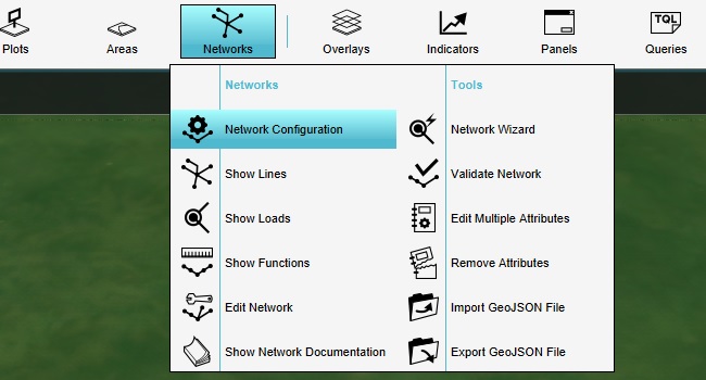
First, activate the electrical network. Select the "Electricity" net type, and then make sure it's activated in the right panel.
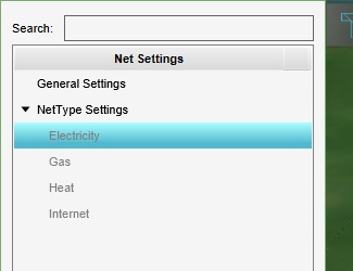
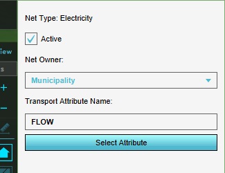
Next, we can draw the network.
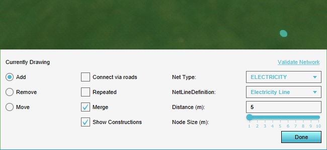
Click in a location in the 3D world to set the first net node location. Click in another location to set the second net node location. You will see a net line appear in the 3D world.
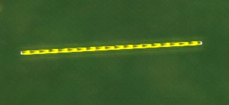
As you move the cursor, you will see a predicted line in bright yellow, which indicates where the next line will be placed when you click again.
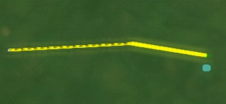
Make the network circle back on itself, letting the last net line connect to one of the intermediate nodes.

Click on the "Add" radio button in the bottom panel to "unfocus" the cursor from the current drawing action. Then click on any node to focus the drawing action there, and create a small offshoot from the network. Repeat this process a few times so the network has a couple of endpoints.
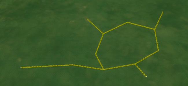
This series of net lines together form a very simple network
