Ground model (Water Overlay): Difference between revisions
| Line 21: | Line 21: | ||
[[File:Undergroundflow.png|right]] | [[File:Undergroundflow.png|right]] | ||
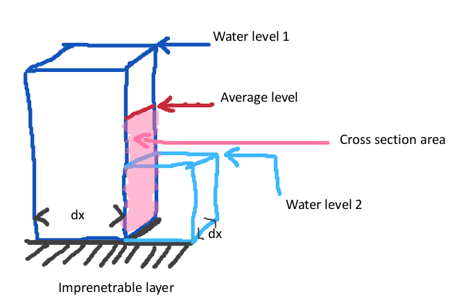
The underground flow is implemented using formulas described in Harbaugh 2005<ref name="Harbaugh"/>. | The underground flow is implemented using formulas described in Harbaugh 2005<ref name="Harbaugh"/>. | ||
See the image to the right. | |||
Two adjacent cells, where underground water level of cell 1 is larger than cell 2. | |||
The flow between the two cells is calculated as: | |||
: Δw = w<sub>1</sub> - w<sub>2</sub> | |||
: B<sub>ex</sub> = max ( B<sub>1</sub> , B<sub>2</sub> ) - D<sub>ground</sub> | |||
: A<sub>c</sub> = Δx * ( w<sub>avg</sub> - B<sub>ex</sub> ) | |||
: C = min(C<sub>1</sub> , C<sub>2</sub> ) | |||
: q = Δw * C * A<sub>c</sub> / Δx * Δt | |||
where | |||
: C<sub>n</sub> = The ground conductance of cell n. For this we use the vertical infiltration speed. | |||
: B<sub>n</sub> = The surface elevation of cell n. | |||
: D<sub>ground</sub> = The configured ground bottom distance. | |||
: w<sub>avg</sub> = Averaged underground water level, based on water levels in underground, underground storage fraction and potentially the surface water level, when the underground is filled to the top. | |||
: A<sub>c</sub> = Area of conductance | |||
: Δt = computational timestep | |||
: Δx = size of grid cell | |||
<br style="clear:both;"> | <br style="clear:both;"> | ||
Revision as of 16:24, 15 April 2019
The Water Module also contains a simplified 2-layer underground model, for infiltration, evaporation and horizontal flow in the underground. Also simplified exfiltration of water from the soil back onto the surface layer is implemented.
The underground model is only active when the GROUND_WATER attribute of the water overlay to 1 or above. Only groundwater overlays set this attribute to 1 by default. If the underground model is not active, water can not infiltrate, exfiltrate, evaporate or flow in/from the underground.
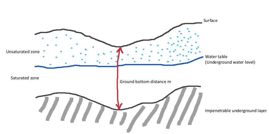
The underground is bounded vertically by the surface of the terrain at the top and by an assumed impenetrable layer at the bottom. The distance between the surface and the impenetrable layer, and thus the effective height of the underground, is equal to GROUND_BOTTOM_DISTANCE_M. In other words, the impenetrable underground layer is assumed to be a set distance below the surface. The distance is uniform across the entire project area, and therefore follows the profile of the surface.
The underground is composed of 2 layers: the unsaturated zone and the saturated zone. The saturated zone is the region of the underground where the soil is saturated with water. This water is assumed to work as a continuous volume of water able to flow horizontally. The unsaturated zone is the region of the underground above the saturated zone. The edge between the unsaturated and saturated zone can be considered the groundwater level.
The groundwater table is the datum height of the top of the saturated zone. The amount of water in the satured zone is determined both the depth of the groundwater table, the GROUND_BOTTOM_DISTANCE_M, and the underground terrain's WATER_STORAGE_PERCENTAGE. Wwhen infiltration and evaporation occur, the groundwater table will fluctuate faster with a lower water storage percentage of the soil.
Initialization
The underground water level is initialized with the values of the ground water GeoTIFF connected to the water model. If no ground water data is connected, the ground water level relative to datum is equal to the surface water level relative to datum, as defined by the WATER_LEVEL attribute of the water level area in that location.
Vertical flow
Vertical underground water flow is modeled as infiltration and described in the subsequent model.
Horizontal flow and aquifers
The underground flow is implemented using formulas described in Harbaugh 2005[1]. See the image to the right. Two adjacent cells, where underground water level of cell 1 is larger than cell 2. The flow between the two cells is calculated as:
- Δw = w1 - w2
- Bex = max ( B1 , B2 ) - Dground
- Ac = Δx * ( wavg - Bex )
- C = min(C1 , C2 )
- q = Δw * C * Ac / Δx * Δt
where
- Cn = The ground conductance of cell n. For this we use the vertical infiltration speed.
- Bn = The surface elevation of cell n.
- Dground = The configured ground bottom distance.
- wavg = Averaged underground water level, based on water levels in underground, underground storage fraction and potentially the surface water level, when the underground is filled to the top.
- Ac = Area of conductance
- Δt = computational timestep
- Δx = size of grid cell
References
- ↑ Harbaugh, A.W., 2005, MODFLOW-2005, the U.S. Geological Survey modular ground-water model-the Ground-Water Flow Process: U.S. Geological Survey Techniques and Methods 6-A16, variously paginated.

