How to set the geo-location of an AutoCAD DXF: Difference between revisions
No edit summary |
No edit summary |
||
| Line 8: | Line 8: | ||
| If the filetype is currently DWG, see this [[How_to_import_a_DXF|how-to]] on how to convert it to a DXF. | | If the filetype is currently DWG, see this [[How_to_import_a_DXF|how-to]] on how to convert it to a DXF. | ||
| Open the DXF file in AutoCAD | | Open the DXF file in AutoCAD | ||
| First make sure the project units of measurement is set to meters, when the | | First make sure the project units of measurement is set to meters, when the CRS of our project is also in meters. See other [[How to set the unit of measurement for a DXF|how-to]]. For EPSG:28992, a project needs to be in meters. | ||
| Next, in the top bar of AutoCAD, go to ''Insert'' and then click on ''Set Location'' on the far right. A new screen pops up. | | Next, in the top bar of AutoCAD, go to ''Insert'' and then click on ''Set Location'' on the far right. A new screen pops up. | ||
| In this popup, fill in a coordinate of your project location in the WGS84 format, that is: ''latitude, longitude'', as seen in the image below and press enter and click next. | | In this popup, fill in a coordinate of your project location in the WGS84 format, that is: ''latitude, longitude'', as seen in the image below and press enter and click next. | ||
| Line 21: | Line 21: | ||
File:Autocad_set_geo_location.PNG|Here you can find the ''Set Location'' option in AutoCAD. | File:Autocad_set_geo_location.PNG|Here you can find the ''Set Location'' option in AutoCAD. | ||
File:Autocad_wgs84_degrees.PNG|Filling in the location of your project in WGS84 Latitude/Longitude degrees. Separate the numbers with a comma. | File:Autocad_wgs84_degrees.PNG|Filling in the location of your project in WGS84 Latitude/Longitude degrees. Separate the numbers with a comma. | ||
File:Autocad_epsg_selection.PNG|Selecting a | File:Autocad_epsg_selection.PNG|Selecting a CRS that is in meters and relevant to your project. Notice the unit of measurement is also in meters by default. If not, you should go back a few steps to configure that correctly. | ||
File:Autocad_type_corresponding _coordinate_in_28992.PNG|Typing the corresponding location in the EPSG:28992 that was selected in the previous step. Do not type spaces between the coordinates, only separate with comma's. | File:Autocad_type_corresponding _coordinate_in_28992.PNG|Typing the corresponding location in the EPSG:28992 that was selected in the previous step. Do not type spaces between the coordinates, only separate with comma's. | ||
File:Autocad_northing_direction_angle.PNG|Provide a northing direction angle. EPSG:28992 points north, so the default of 90 degrees is provided. | File:Autocad_northing_direction_angle.PNG|Provide a northing direction angle. EPSG:28992 points north, so the default of 90 degrees is provided. | ||
Revision as of 09:29, 1 December 2022
DWG files can be indirectly imported into a Project, by first converting them to a DXF file (the open-standard equivalent). DXF files can then be imported directly through the Geo Data Wizard, as either features in the Current Situation, or in the Future Design. However, it is important that the entities and objects in the DXF file are at the correct Geo-location. AutoCAD itself does not geo-transforms coordinates. Instead, you select a project location, and tell autocad what the coordinates are in WGS84 Lat/Long and what the corresponding coordinates are in coordinate system that you want to use. Additionally you have to provide what the northing axis of the coordinate system is.
The following how-to describes how to set the Geo-location of a DXF in the Dutch coordinate system EPSG:29882. This how to is based on the steps described on an autodesk forum[1].
- If the filetype is currently DWG, see this how-to on how to convert it to a DXF.
- Open the DXF file in AutoCAD
- First make sure the project units of measurement is set to meters, when the CRS of our project is also in meters. See other how-to. For EPSG:28992, a project needs to be in meters.
- Next, in the top bar of AutoCAD, go to Insert and then click on Set Location on the far right. A new screen pops up.
- In this popup, fill in a coordinate of your project location in the WGS84 format, that is: latitude, longitude, as seen in the image below and press enter and click next.
- In the following screen, select the coordinate system relevant to your project location. For projects in the Netherlands, select 28992. Also make sure the Drawing unit is set to meters. If you have performed the how-to on how to setup your projects drawing unit, then this dropdown should show meters.
- Click next.
- This step is Important: Notice the command input below indicates: GEOGRAPHICLOCATION: Select a point for the location. You now have to select this bar, and fill in the converted coordinate in the CRS that you selected to align the geo-location with the location in your CRS. If you do not know how to convert coordinates, see the how-to on How to convert a coordinate from one CRS to another. See also the image below with the converted coordinate correctly filled in.
- The project should now have configured the geo location correctly and satellite imagery should be visualized.
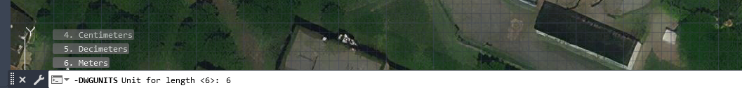
Typing -DWGUNITS to start a mini wizard in AutoCAD to set the project unit of measurement to meters. See how-to.
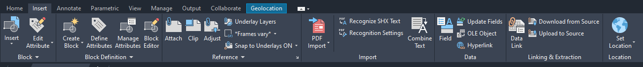
Here you can find the Set Location option in AutoCAD.
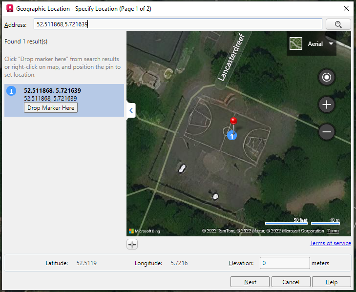
Filling in the location of your project in WGS84 Latitude/Longitude degrees. Separate the numbers with a comma.
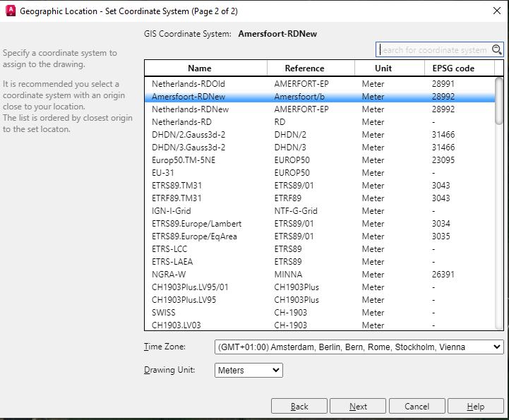
Selecting a CRS that is in meters and relevant to your project. Notice the unit of measurement is also in meters by default. If not, you should go back a few steps to configure that correctly.

Typing the corresponding location in the EPSG:28992 that was selected in the previous step. Do not type spaces between the coordinates, only separate with comma's.
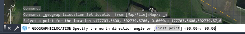
Provide a northing direction angle. EPSG:28992 points north, so the default of 90 degrees is provided.


Notes
- Layers do not need to be visible to include them in the import.
- In AutoCAD, the satellite imagery does not always correctly align with the provided coordinates. You can double check the correctness of imagery and locations in other software, such as QGIS.
- When importing a DXF file, each feature will have an Attribute indicating its layer, and an Attribute COLOR_INDEX indicating its color (index). It also has an additional Attribute COLOR, in which the feature's color in the original file is translated to a Tygron Color code.
References
- ↑ Export image has incorrect coordinates, Message 9 of 10 ∙ ChicagoLooper in reply to: nano.langenheim ∙ Found at: https://forums.autodesk.com/t5/autocad-raster-design-forum/export-image-has-incorrect-coordinates/td-p/9365778 ∙ (last visited: 30-11-2022)