Ground model (Water Overlay): Difference between revisions
No edit summary |
No edit summary |
||
| (22 intermediate revisions by the same user not shown) | |||
| Line 1: | Line 1: | ||
<gallery widths=500px heights=300px> | |||
File:Water_module_layers.jpeg | |||
File:Water_module_flows.jpeg | |||
</gallery> | |||
The Water Module also contains a simplified | The Water Module also contains a simplified multi-layer ground model, for [[Infiltration model (Water Overlay)|infiltration]], [[Evaporation model (Water Overlay)|evapotranspiration]], [[#Bottom flow|bottom flow]] and [[#Horizontal flow and aquifers|horizontal flow]] in the ground layer. Additionally, the model also applies a simplified form of exfiltration of water from the soil back onto the surface layer. | ||
==Groundwater modes== | ==Groundwater modes== | ||
| Line 9: | Line 12: | ||
* Complete (selected by default for the [[Groundwater_(Overlay)|groundwater overlay]]) | * Complete (selected by default for the [[Groundwater_(Overlay)|groundwater overlay]]) | ||
== | ==Multi Layered model== | ||
The assumption is made that | The assumption is made that ground is bound vertically by the [[terrain height (Water Overlay)|surface of the terrain]] at the top and by an impenetrable layer at the bottom. The distance between the surface and the impenetrable layer, and thus the effective height of the ground, is equal to [[Ground bottom distance m model attribute (Water Overlay)|ground bottom distance]]. In other words, the impenetrable ground layer is assumed to be a set distance below the surface. The distance is uniform across the entire project area, and thus the impenetrable follows the profile of the surface. | ||
The fraction of water the | The fraction of water the ground can store per volume is defined with the [[Terrain water storage percentage (Water Overlay)|WATER_STORAGE_PERCENTAGE]] attribute of the ground layer terrain. | ||
The | The ground layer is modeled using two layers: the '''unsaturated zone''' and the '''saturated zone'''. The saturated zone is the region of the ground where the soil is fully saturated with water. The unsaturated zone is the region of the ground located directly above the saturated zone. This region can also contain water, but the amount contained is always less than the maximum storage fraction. Water in the unsaturated zone is assumed to be uniformly distributed across the entire height of the zone. | ||
The edge between the unsaturated and saturated zone is defined as the ''groundwater level'', also known as the watertable. | The edge between the unsaturated and saturated zone is defined as the ''groundwater level'', also known as the watertable. | ||
The groundwater table is the height of the top of the saturated zone, relative to {{datum}}. The amount of water in the saturated zone is determined with the {{datum}} height of the groundwater table, the {{datum}} height of the surface, the [[Ground bottom distance m model attribute (Water Overlay)| | The groundwater table is the height of the top of the saturated zone, relative to {{datum}}. The amount of water in the saturated zone is determined with the {{datum}} height of the groundwater table, the {{datum}} height of the surface, the [[Ground bottom distance m model attribute (Water Overlay)|ground bottom distance]] and the ground terrain's [[Terrain water storage percentage (Water Overlay)|WATER_STORAGE_PERCENTAGE]]. | ||
===Initialization=== | ===Initialization=== | ||
The | The ground water level is initialized with the values of the [[Groundwater Prequel (Water Overlay)|ground water prequel]] connected to the water model. If no ground water data is connected, the ground water level relative to {{datum}} is equal to the surface water level relative to {{datum}}, as defined by the [[Water level (Water Overlay)|WATER_LEVEL]] attribute of the [[Water area (Water Overlay)|water area]] in that location. If no water area exists there either, the groundwater level is set to one meter below the [[elevation model (Water Overlay)|surface]]. | ||
===Vertical flow=== | ===Vertical flow=== | ||
Vertical | Vertical ground water flow is modeled as [[Infiltration model (Water Overlay)|infiltration]] and [[Evaporation model (Water Overlay)|evapotranspiration]]. | ||
===Horizontal flow and aquifers=== | ===Horizontal flow and aquifers=== | ||
Ground flow is different from surface flow, since it has to account for the slowdown and porousness of the medium. In general, [[Ground flow formula (Water Overlay)|horizontal ground flow]] is calculated using formulas described in Harbaugh 2005<ref name="Harbaugh"/><ref name="Modflow"/>. Depending on the [[Hydraulic conductivity with thickness (Water Overlay)|configuration of the Water Overlay ]], the flow can also be calculated using a [[Terrain hydraulic conductivity with thickness md (Water Overlay)|KD]] values instead of [[Terrain hydraulic conductivity md (Water Overlay)|K]]. However, when an [[Aquifer (Water Overlay)|aquifer]] is present, the [[Ground flow formula (Water Overlay)#Aquifer formula|horizontal aquifer flow]] variant is applied. | |||
[[File:Undergroundflow2.png|left]] | [[File:Undergroundflow2.png|left]] | ||
{{clear}} | {{clear}} | ||
=== | ===Bottom flow=== | ||
Water can also | Water can also flow into the ground layer from deeper confined layers due to pressure from higher regions outside the project area. The speed at which the [[Ground bottom flow formula (Water Overlay)|ground bottom flow]] occurs is dependent on the local ground water levels, the [[Bottom pressure prequel (Water Overlay)|head (pressure) of the higher regions]] and the [[Bottom resistance prequel (Water Overlay)|resistance of the layer]] separating the saturated zone of the freatic ground layer and deeper ground layer. | ||
Note that | Note that ground bottom flow can also be negative, allowing water to flow out of the project area to the deeper confined layers to regions elsewhere. | ||
===Drainage=== | ===Drainage=== | ||
Drainages provide connections between the | [[Drainage (Water Overlay)|Drainages]] are hydraulic structures that provide connections between the ground and nearby waterways, draining groundwater to levels which are optimal for agriculture. Drainage can be passive, where water drains based on water head differences, or active, where the water is pumped from the drain to the nearby waterway. Additionally, the datum height below ground and the overflow height in the waterway can be configured. | ||
{{article end | {{article end | ||
|notes= | |notes= | ||
* The [[sewer model (Water Overlay)|sewer]] is explicitly ''not'' part of the | * The [[sewer model (Water Overlay)|sewer]] is explicitly ''not'' part of the ground model, and is not affected by the [[Ground water (Water Overlay)|GROUND_WATER]] attribute nor by the ground model directly. | ||
|related= | |related= | ||
The following topics are related to this models. | The following topics are related to this models. | ||
; Formulas | ; Formulas | ||
: [[Groundwater level formula (Water Overlay)]] | : [[Groundwater level formula (Water Overlay)]] | ||
: [[ | : [[Ground flow formula (Water Overlay)]] | ||
: [[ | : [[Ground evaporation formula (Water Overlay)]] | ||
: [[Surface infiltration formula (Water Overlay)]] | : [[Surface infiltration formula (Water Overlay)]] | ||
: [[ | : [[Ground bottom flow formula (Water Overlay)]] | ||
: [[ | : [[Ground infiltration formula (Water Overlay)]] | ||
; Models | ; Models | ||
: [[Surface model (Water Overlay)]] | : [[Surface model (Water Overlay)]] | ||
| Line 58: | Line 61: | ||
: [[Infiltration model (Water Overlay)]] | : [[Infiltration model (Water Overlay)]] | ||
: [[Tracer flow model (Water Overlay)]] | : [[Tracer flow model (Water Overlay)]] | ||
|references= | |references= | ||
<references> | <references> | ||
Latest revision as of 15:03, 5 March 2024
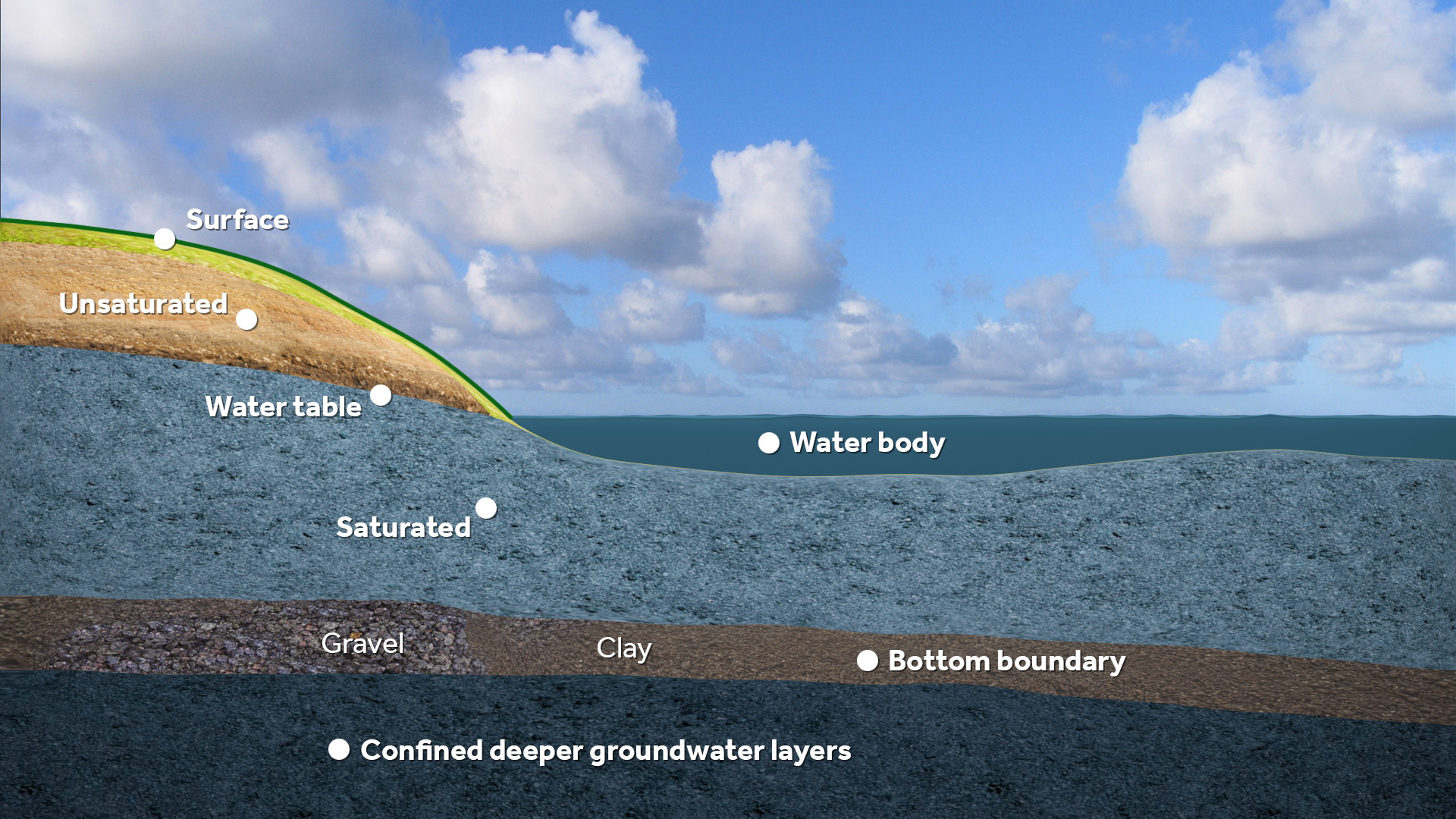
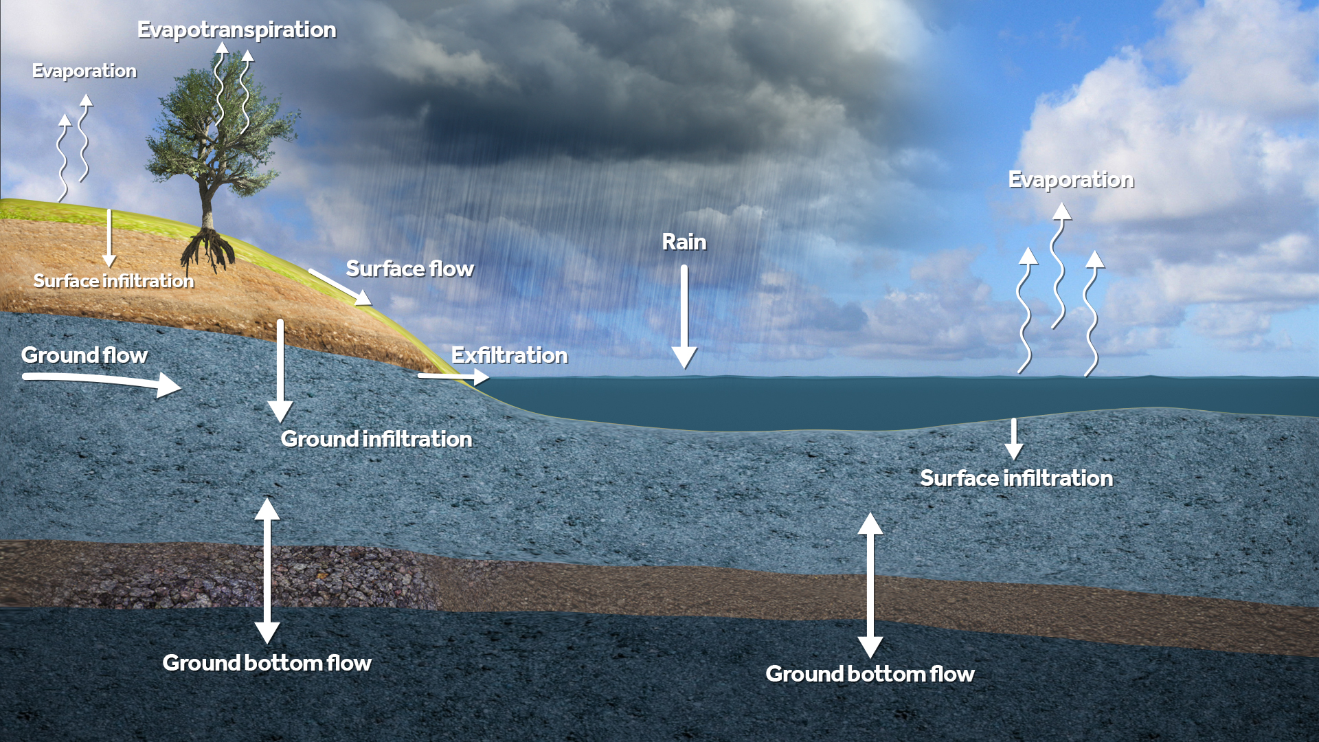
The Water Module also contains a simplified multi-layer ground model, for infiltration, evapotranspiration, bottom flow and horizontal flow in the ground layer. Additionally, the model also applies a simplified form of exfiltration of water from the soil back onto the surface layer.
Groundwater modes
For the Water Module there exist three modes for handling groundwater:
- None
- Infiltration only (selected by default for the flooding and rainfall overlay)
- Complete (selected by default for the groundwater overlay)
Multi Layered model
The assumption is made that ground is bound vertically by the surface of the terrain at the top and by an impenetrable layer at the bottom. The distance between the surface and the impenetrable layer, and thus the effective height of the ground, is equal to ground bottom distance. In other words, the impenetrable ground layer is assumed to be a set distance below the surface. The distance is uniform across the entire project area, and thus the impenetrable follows the profile of the surface.
The fraction of water the ground can store per volume is defined with the WATER_STORAGE_PERCENTAGE attribute of the ground layer terrain.
The ground layer is modeled using two layers: the unsaturated zone and the saturated zone. The saturated zone is the region of the ground where the soil is fully saturated with water. The unsaturated zone is the region of the ground located directly above the saturated zone. This region can also contain water, but the amount contained is always less than the maximum storage fraction. Water in the unsaturated zone is assumed to be uniformly distributed across the entire height of the zone.
The edge between the unsaturated and saturated zone is defined as the groundwater level, also known as the watertable.
The groundwater table is the height of the top of the saturated zone, relative to datum. The amount of water in the saturated zone is determined with the datum height of the groundwater table, the datum height of the surface, the ground bottom distance and the ground terrain's WATER_STORAGE_PERCENTAGE.
Initialization
The ground water level is initialized with the values of the ground water prequel connected to the water model. If no ground water data is connected, the ground water level relative to datum is equal to the surface water level relative to datum, as defined by the WATER_LEVEL attribute of the water area in that location. If no water area exists there either, the groundwater level is set to one meter below the surface.
Vertical flow
Vertical ground water flow is modeled as infiltration and evapotranspiration.
Horizontal flow and aquifers
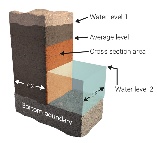
Ground flow is different from surface flow, since it has to account for the slowdown and porousness of the medium. In general, horizontal ground flow is calculated using formulas described in Harbaugh 2005[1][2]. Depending on the configuration of the Water Overlay , the flow can also be calculated using a KD values instead of K. However, when an aquifer is present, the horizontal aquifer flow variant is applied.
Bottom flow
Water can also flow into the ground layer from deeper confined layers due to pressure from higher regions outside the project area. The speed at which the ground bottom flow occurs is dependent on the local ground water levels, the head (pressure) of the higher regions and the resistance of the layer separating the saturated zone of the freatic ground layer and deeper ground layer.
Note that ground bottom flow can also be negative, allowing water to flow out of the project area to the deeper confined layers to regions elsewhere.
Drainage
Drainages are hydraulic structures that provide connections between the ground and nearby waterways, draining groundwater to levels which are optimal for agriculture. Drainage can be passive, where water drains based on water head differences, or active, where the water is pumped from the drain to the nearby waterway. Additionally, the datum height below ground and the overflow height in the waterway can be configured.
Notes
- The sewer is explicitly not part of the ground model, and is not affected by the GROUND_WATER attribute nor by the ground model directly.
Related
The following topics are related to this models.
- Formulas
- Groundwater level formula (Water Overlay)
- Ground flow formula (Water Overlay)
- Ground evaporation formula (Water Overlay)
- Surface infiltration formula (Water Overlay)
- Ground bottom flow formula (Water Overlay)
- Ground infiltration formula (Water Overlay)
- Models
- Surface model (Water Overlay)
- Evaporation model (Water Overlay)
- Infiltration model (Water Overlay)
- Tracer flow model (Water Overlay)
References
- ↑ Harbaugh, A.W., 2005, MODFLOW-2005, the U.S. Geological Survey modular ground-water model-the Ground-Water Flow Process: U.S. Geological Survey Techniques and Methods 6-A16, variously paginated.
- ↑ Langevin, C.D., Hughes, J.D., Banta, E.R., Niswonger, R.G., Panday, Sorab, and Provost, A.M. (2017) ∙ Documentation for the MODFLOW 6 Groundwater Flow Model: U.S. Geological Survey Techniques and Methods, book 6, chap. A55 ∙ p 31 ∙ found at: https://doi.org/10.3133/tm6A55 (last visited 2019-02-04)


