Sky view factor calculation model (Heat Overlay): Difference between revisions
No edit summary |
No edit summary |
||
| (25 intermediate revisions by 5 users not shown) | |||
| Line 1: | Line 1: | ||
The sky view factor is a measure of how much of the sky is visible from any given location. It is an important factor used in the calculations of the [[DPRA Heat Module]]. | |||
== | ==Implementation== | ||
The sky view factor is computed for each grid cell, based on features in the project area which block sight of the sky, and the resulting angles across which a direct line of sight to the sky is possible. The visible sections of the sky computed in this way are mapped onto a 2D flat surface. In literature this is dubbed the "sky view area", and may also be referred to here as the "projected circle". | |||
{{clear|both}} | |||
===Determining sky limiters=== | |||
The model starts by determining per grid cell what the height of obstacles are on that grid cell. An obstacle can be: | The model starts by determining per grid cell what the height of obstacles are on that grid cell. An obstacle can be: | ||
* a building, | * a building, | ||
| Line 14: | Line 11: | ||
* terrain height. | * terrain height. | ||
The sky view factor is calculated at a height of 1.2 meters above the surface, which is an assumption of body height. In this model, the surface includes [[building]]s (thus the calculation would take place on top of any buildings present), but does not include foliage height. | |||
{{clear|both}} | |||
The sky | ===Computing rays=== | ||
[[File:Sky_view_limiters.png|thumb|right|The closer to any given location, and the higher a sky limiter, the smaller the section of the sky that is visible.]] | |||
The area of a sky view section is calculated as followed: | The area of a sky view section is calculated as followed: | ||
First the top down view is considered. | First the top down view is considered. To determinee the amount of rays that will be cast, the following scheme is applied: | ||
A unique ray is cast for each gray cell. Each gray cell also functions as a unique ray end point. The colored cells indicate the cells visited for a particular ray. Each cell has a height of a building, terrain or foliage. | A unique ray is cast for each gray cell. Each gray cell also functions as a unique ray end point. The colored cells indicate the cells visited for a particular ray. Each cell has a height of a building, terrain or foliage. The maximum search range is currently 100 meters. | ||
{{clear|left}} | |||
[[File:Sky_view_grid1.png|300px]][[File:Sky_view_grid2.png|300px]][[File:Sky_view_grid3.png|300px]] | [[File:Sky_view_grid1.png|300px]][[File:Sky_view_grid2.png|300px]][[File:Sky_view_grid3.png|300px]] | ||
The sky view sections are formed by each consecutive pair of rays. | The sky view sections are formed by each consecutive pair of rays. The greater the search radius, the more cells compose the circle, and thus the more rays are cast. Similarly, the smaller the grid cell size, the more cells compose the circle, and the more rays are cast. | ||
For each ray, the maximum view angle is determined by traveling from the center along the ray and reevaluating the view angle based on the building, foliage and terrain height. | For each ray, the maximum view angle is determined by traveling from the center along the ray and reevaluating the view angle based on the building, foliage and terrain height. | ||
Next, once the maximum view angle is determined, the ray can be projected onto the horizontal plane. | Next, once the maximum view angle is determined, the ray can be projected onto the horizontal plane. | ||
<gallery mode="nolines"> | |||
File:Sky_view_angle1.png|300px|Rays are drawn based on the height of sky limiting features. | |||
File:Sky_view_angle2.png|300px|The dark green line indicates the resulting projection onto the 2D plane. | |||
</gallery> | |||
[[File:Sky_view_sections.png|thumb|right|The section of the sky that is visible from any given location is projected onto a 2D plane. This projection is the sky view section.]] | |||
A sky view section is formed by determining the average length of two consecutive rays, and drawing the arc between them using the averaged length. | |||
[[File:Sky_view_projected_rays.png|400px]][[File:Sky_view_projected_area.png|400px]] | [[File:Sky_view_projected_rays.png|400px]][[File:Sky_view_projected_area.png|400px]] | ||
{{clear|left}} | |||
The average projected ray length from these two rays r1 and r2 are used to calculate the area of sky view section ''i'': | |||
<math>\alpha = \arccos{(x_{r1} x_{r2} + y_{r1} y_{r2})}</math> | <math>\alpha = \arccos{(x_{r1} x_{r2} + y_{r1} y_{r2})}</math> | ||
| Line 45: | Line 45: | ||
<math>area_i = \frac{\alpha}{2\pi} \pi {(r_{avg})}^2</math> | <math>area_i = \frac{\alpha}{2\pi} \pi {(r_{avg})}^2</math> | ||
{{clear|both}} | |||
===Sky view area=== | |||
[[File:Sky_view_area.png|thumb|right|All sky view sections together form the sky view area. The ratio of the sky view area to the total (potential) view area is the sky view factor.]] | |||
The sky view area is then calculated as the sum of the areas of sky view sections. | The sky view area is then calculated as the sum of the areas of sky view sections. | ||
With the sky view area, the sky view factor can be calculated by dividing the sky view area by the area of the circle of the horizontal plane. | With the sky view area, the sky view factor can be calculated by dividing the sky view area by the area of the circle of the horizontal plane. | ||
<math>svf=\sum_{1}^n \frac{area_i}{\pi r^2}</math> | <math>svf=\sum_{1}^n \frac{area_i}{\pi r^2}</math> | ||
{{clear|both}} | |||
==Sky view factor instead of sky exposure factor== | |||
In literature, two sky parameters are mentioned which is sometimes confusing; Sky exposure and sky view factor. The sky exposure is related to the sky view dome (3D). The sky view factor is related to the projection of the view dome to the horizontal plane (2D). | |||
The {{software}} uses the sky view factor rather than sky exposue, because the sky view factor result weights objects closer to the top of the sky view dome higher than objects further away. This is caused by the projection from 3D to 2D. This is desirable, because the sky view factor is directly related to the reflected radiation in the used formulas. | |||
{{article end | |||
|notes= | |||
* The size of the dome and sky circle on the horizontal plane do not matter. They can simply be a unit sphere and circle. Only the angle between the ray and the horizontal plane determine the sky view sections. | * The size of the dome and sky circle on the horizontal plane do not matter. They can simply be a unit sphere and circle. Only the angle between the ray and the horizontal plane determine the sky view sections. | ||
* The sky view factor of cells situated under foliage are always calculated as 0, in accordance with section 3.4.5.1 of the [[DPRA Heat stress report]]{{ref|skyviewfactor}}. | |||
|seealso= | |||
* [[Sky_view_result_type_(Heat_Overlay)|Sky view factor result]] | |||
* [[Average calculation model (Heat Overlay)]] | |||
|references= | |||
<references> | |||
{{ref|skyviewfactor | |||
|name=Ontwikkeling Standaard Stresstest Hitte | |||
|author=Kurganov A, Petrova G (2019) | |||
|page= | |||
|source= | |||
|link=https://www.rivm.nl/bibliotheek/rapporten/2019-0008.pdf | |||
|lastvisit=2024-03-15 | |||
}} | |||
</references> | |||
}} | |||
{{Template:HeatOverlay_formula_nav}} | |||
Latest revision as of 14:31, 17 October 2025
The sky view factor is a measure of how much of the sky is visible from any given location. It is an important factor used in the calculations of the DPRA Heat Module.
Implementation
The sky view factor is computed for each grid cell, based on features in the project area which block sight of the sky, and the resulting angles across which a direct line of sight to the sky is possible. The visible sections of the sky computed in this way are mapped onto a 2D flat surface. In literature this is dubbed the "sky view area", and may also be referred to here as the "projected circle".
Determining sky limiters
The model starts by determining per grid cell what the height of obstacles are on that grid cell. An obstacle can be:
- a building,
- foliage, such as trees; The top of foliage is used as the obstacle height;
- terrain height.
The sky view factor is calculated at a height of 1.2 meters above the surface, which is an assumption of body height. In this model, the surface includes buildings (thus the calculation would take place on top of any buildings present), but does not include foliage height.
Computing rays
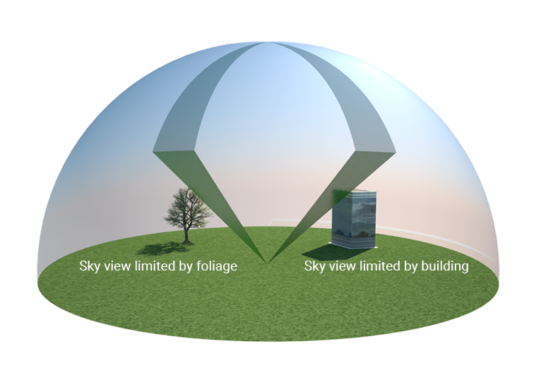
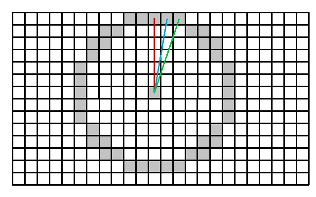
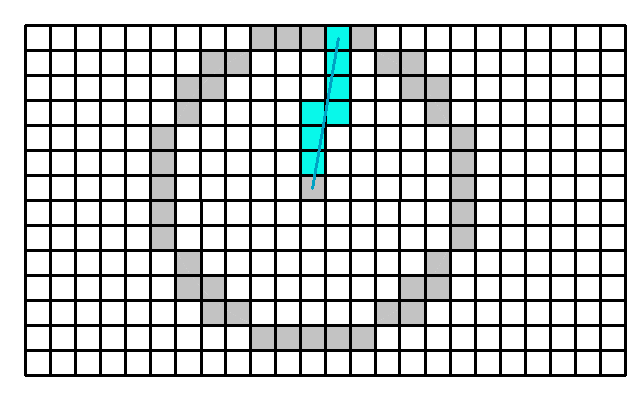
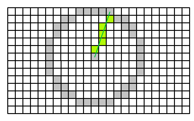
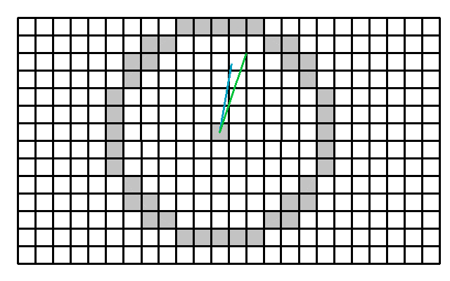
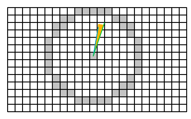
The area of a sky view section is calculated as followed: First the top down view is considered. To determinee the amount of rays that will be cast, the following scheme is applied: A unique ray is cast for each gray cell. Each gray cell also functions as a unique ray end point. The colored cells indicate the cells visited for a particular ray. Each cell has a height of a building, terrain or foliage. The maximum search range is currently 100 meters.
The sky view sections are formed by each consecutive pair of rays. The greater the search radius, the more cells compose the circle, and thus the more rays are cast. Similarly, the smaller the grid cell size, the more cells compose the circle, and the more rays are cast.
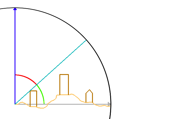
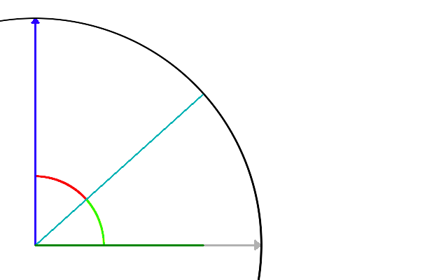
For each ray, the maximum view angle is determined by traveling from the center along the ray and reevaluating the view angle based on the building, foliage and terrain height. Next, once the maximum view angle is determined, the ray can be projected onto the horizontal plane.
-
Rays are drawn based on the height of sky limiting features.
-
The dark green line indicates the resulting projection onto the 2D plane.
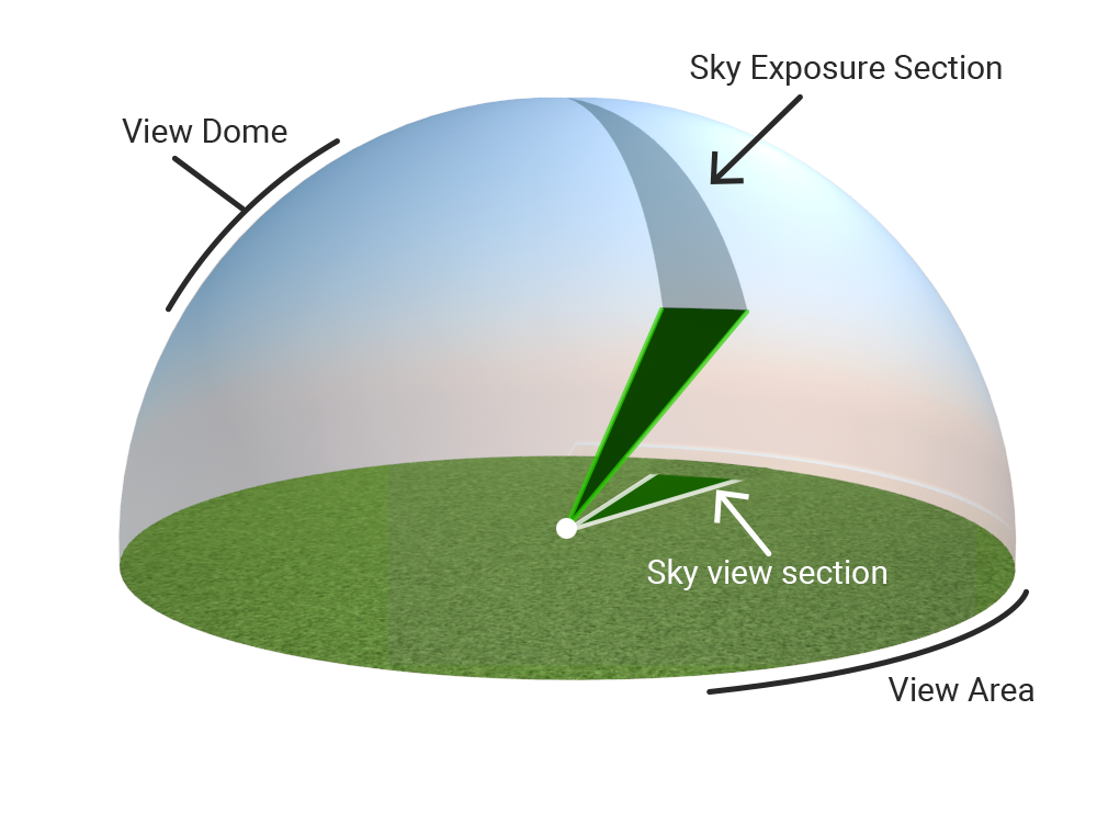
A sky view section is formed by determining the average length of two consecutive rays, and drawing the arc between them using the averaged length.
The average projected ray length from these two rays r1 and r2 are used to calculate the area of sky view section i:
Sky view area
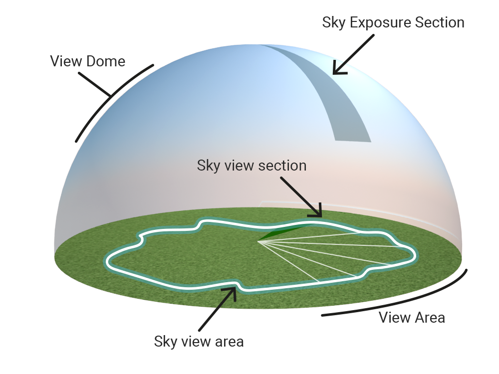
The sky view area is then calculated as the sum of the areas of sky view sections. With the sky view area, the sky view factor can be calculated by dividing the sky view area by the area of the circle of the horizontal plane.
Sky view factor instead of sky exposure factor
In literature, two sky parameters are mentioned which is sometimes confusing; Sky exposure and sky view factor. The sky exposure is related to the sky view dome (3D). The sky view factor is related to the projection of the view dome to the horizontal plane (2D).
The Tygron Platform uses the sky view factor rather than sky exposue, because the sky view factor result weights objects closer to the top of the sky view dome higher than objects further away. This is caused by the projection from 3D to 2D. This is desirable, because the sky view factor is directly related to the reflected radiation in the used formulas.
Notes
- The size of the dome and sky circle on the horizontal plane do not matter. They can simply be a unit sphere and circle. Only the angle between the ray and the horizontal plane determine the sky view sections.
- The sky view factor of cells situated under foliage are always calculated as 0, in accordance with section 3.4.5.1 of the DPRA Heat stress report[1].
See also
References
- ↑ Ontwikkeling Standaard Stresstest Hitte ∙ Kurganov A, Petrova G (2019) ∙ Found at: https://www.rivm.nl/bibliotheek/rapporten/2019-0008.pdf ∙ (last visited: 2024-03-15)
