Terrain height
Terrain height
- Terrain height is the whole of differences of terrain elevation in a given area, the quantitative measurement of vertical elevation change in a landscape. Terrain is used here as a general term in physical geography, referring to the lay of the land. This is usually expressed in terms of the elevation, slope, and orientation of terrain features. Terrain height - as element of a terrain - affects surface water flow and distribution. Over a large area, it can affect weather and climate patterns.
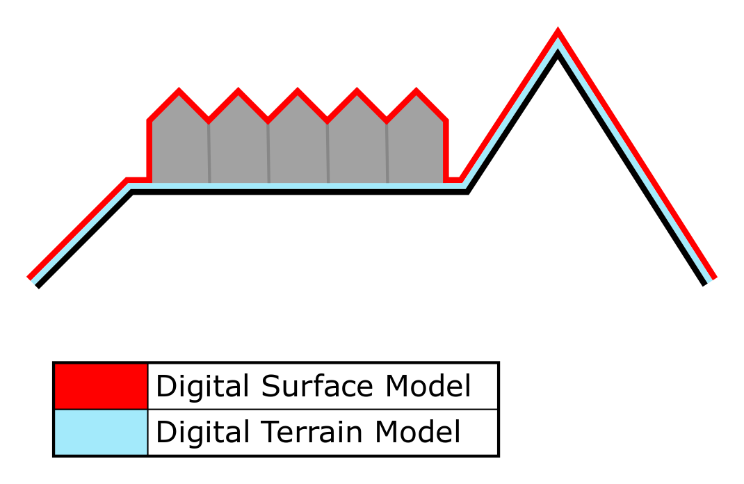
- In overlays, the user can select two types of elevation, the digital terrain model (DTM) and digital surface model (DSM). A DTM represents the bare ground surface without any objects like plants and buildings. In contrast; a DSM represents the earth's surface including all objects (e.g. houses, trees, etc.) on it.
- View original file here:[1]
Terrain height in the Tygron Platform
DTM for projects in The Netherlands
Data sources
In the Netherlands a DTM is constructed using the following data sources:
- A base DTM, with a cell size of 3mx3m, supplied by Rijkswaterstaat to ESRI, based on the AHN2.
- A DSM from AHN2 or AHN3 raw data (Actuele Hoogte Bestand) with a cell-size of 0.5x0.5m, 1x1m or 2.5x2.5m.
- A DTM from AHN2 or AHN3 containing interpolated ("maaiveld") data from ESRI, with a cell-size of 0.5x0.5m, 1x1m or 2.5x2.5m.
- BGT or Top10NL data.
Options
When defining a new project, you can adjust the following Advanced Options at the wizard to control the DTM and DSM data used. These options are:
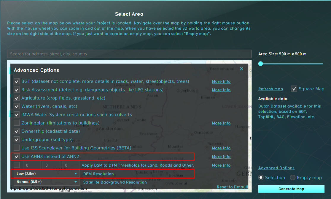
- Use AHN3 DSM instead of AHN2: by default the AHN3 will be used for both the DTM and DSM. When not selected, the AHN2 data is used for the DTM and DSM.
- DEM Resolution: The AHN is available on 0.5m, 1m or 2.5m resolution in the project database for generating the elevation grid (see the image below). Select the resolution appropriate for your project's needs.
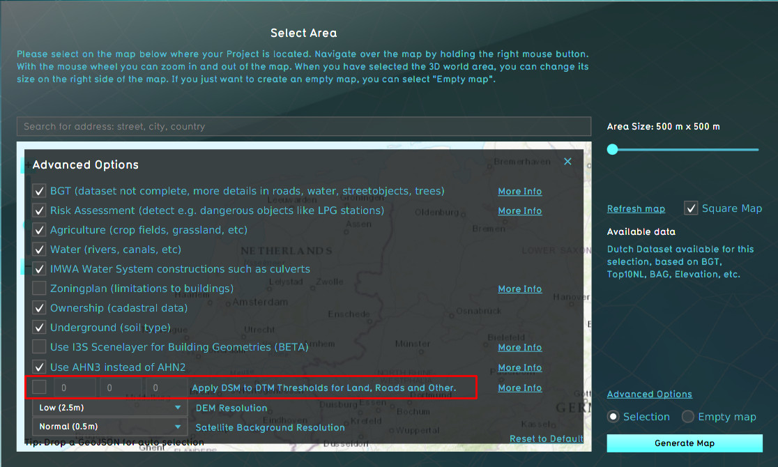
- Apply DSM to DTM Thresholds for Land, Roads, and Other: Optionally, the AHN DSM data can be applied to the DTM for height differences below the provided thresholds, based on the topography. This option can be useful when the DTM is too much averaged and smoothed and more variation is desirable. By default however, this option is turned off. When selected, the thresholds and resulting behavior will be:
- for bare lands the default threshold is 100cm: for all cells with a difference <100cm between the DTM and DSM, the value will be taken from the DSM
- for roads the default threshold is 25cm: for all cells with a difference <25cm between the DTM and DSM, the value will be taken from the DSM
- for crop-lands, scrup-land, etc the default threshold is 50cm: for all cells with a difference <50cm between the DTM and DSM, the value will be taken from the DSM
It is possible to change the default thresholds. To do so, change the corresponding value in the Advanced Options menu (see the image below). The first value is for bare lands, the second for the roads and the third for the crop-lands etc.
DTM generation
A project's DTM is created with the following steps:
- The ESRI DTM is resampled to the same resolution of the AHN DTM and AHN DSM.
- The AHN DTM is set as the base DTM.
- The ESRI DTM is used to replace the NO_DATA values in the DTM, which can be present at waterbodies.
- Optionally, depending on the selected DSM to DTM advanced option, the DSM is applied to the DTM based on the topology value and the configured thresholds:
- for bare lands, all cells with a difference between the DTM and DSM < the first threshold, the value will be taken from the DSM
- for roads, all cells with a difference between the DTM and DSM < the second threshold, the value will be taken from the DSM
- for crop-lands, scrup-land etc, all cells with a difference between the DTM and DSM < the third threshold, the value will be taken from the DSM
DSM usage
Rooftops of buildings receive an average height of the DSM of the polygon defining the buildings footprint. The footprint is split into sections using image recognition techniques; herewith the variability in rooftops can be taken into account in the elevation model
Waterdepth
Water bodies, found in terrain surface types, are lowered a few meters relative to the elevation of the surrounding surface. By default:
- Boezemwater: 3m lowered relative to the elevation of the surrounding surface
- Water: 2m lowered relative to the elevation of the surrounding surface
These values can be changed by changing the WATER_DEPTH_M attribute of the Terrain type. From the DEM a heightpoint in or as close to the wateredge is taken. On that point the Underground terrain type is determined. The slope (talud) of the sides of the water body is defined by the ANGLE_OF_REPOSE of this Underground Terrain Types and the maximum depth to which a water body is carved out is WATER_DEPTH_M as defined for the surface terrain type on this point. If the angle of repose is shallow enough and the water body thin enough, the angled sides may meet up before the maximum water depth is reached. In this case the water body will be appropriately shallower. The ANGLE_OF_REPOSE attribute can also be changed.
How-to's
- How to import a GeoJSON to change the elevation model
- How to import a GeoTIFF to change the elevation model
- How to import a GeoJSON of waterways
- How to import a GeoTIFF of waterway depths
- How to use the terrain height brush in selection mode
- How to use the terrain height brush in live sculpting mode


