Rainfall Overlay
What is the Rainfall overlay?
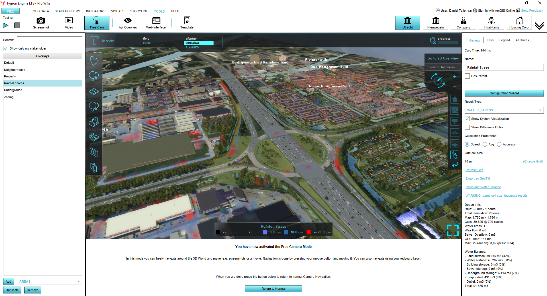
The rainfall overlay is an Overlay displaying the hazard and impact of heavy rainfall over the project area. Based on the elevation model, terrain roughness and representations of the sewer and water systems, several result types can be displayed.
Adding and removing
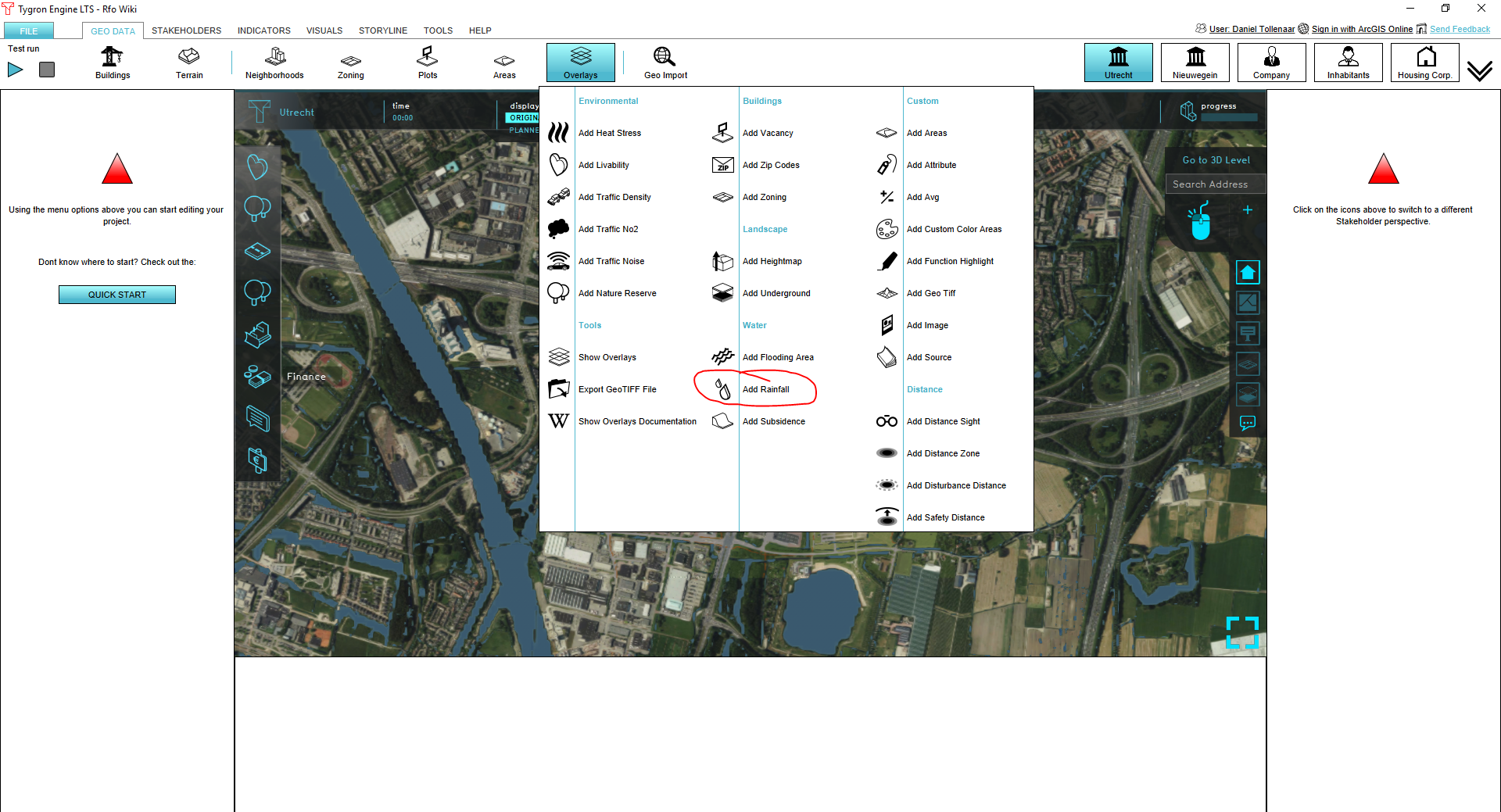
To add a rainfall overlay go to the Overlays menu in the GEO DATA ribbon and select Add Rainfall. To remove the overlay, press Remove below the overlays list.
A Rainfall Overlay Tutorial is available to start working with this overlay.
Result types
The rainfall overlay is a grid overlay showing results of heavy rainfall on the surface (flooding), sub-surface (groundwater), open water and sewer system. The following results are produced:
| Result type | Unit | Description |
|---|---|---|
| BASE_GROUNDWATER_DISTANCE | m (below surface) | Initial groundwater level relative to the surface level (NL: ontwateringsdiepte). |
| BASE_TYPES | nominal value | Division of gridcells in water, land or sewer areas that are connected to the sewer. |
| EVAPORATED | m (mm)¹ | Total evaporation over the simulation period |
| IMPACTED_BUILDINGS | nominal value | Constructions impacted by flood: the value from the function value indicator is assigned to a building if the water depth at a grid-cell surrounding the building exceeds the overlay attribute value IMPACT_FLOOD_TRESHOLD_M |
| SEWER_LAST_VALUE | m (mm)¹ | The amount of water in the sewer storage at the end of simulation |
| SEWER_MAX_VALUE | m (mm)¹ | Maximum amount of water in the sewer storage during the simulation |
| SURFACE_DURATION | s (min)¹ | The amount of time the water depth in a cell exceeds the value set in the overlay attribute value SHOW_DURATION_FLOOD_LEVEL_M |
| SURFACE_FLOW | m3/m2 | Total volume of water passed a grid-cell, scaled by the cell surface (grid cell-size^2) |
| SURFACE_LAST_VALUE | m (min)¹ | Water depth at the end of simulation |
| SURFACE_MAX_VALUE | m (min)¹ | Maximum water depth during the simulation |
| UNDERGROUND_FLOW | m³/m² | Totall infiltration amount from the surface to groundwater |
| UNDERGROUND_LAST_VALUE | m (mm) | The amount by which the groundwater table has risen above the initial groundwater level at the end of simulation |
| UNDERGROUND_MAX_VALUE | m (mm) | The maximum amount by which the groundwater table has risen above the initial groundwater during the simulation |
| WATER_STRESS | m (mm) | The Maximum water depth during the simulation. At water cells only a water depth is shown if the depth exceeds the overlay attribute value ALLOWED_WATER_INCREASE_M |
¹ the units between () are as displayed in the 3D client. If exported to GTiff the SI-convention is used: meters (m) and seconds (s).
Rainfall Overlay Model
The Rainfall Overlay Model will be described in this seciton
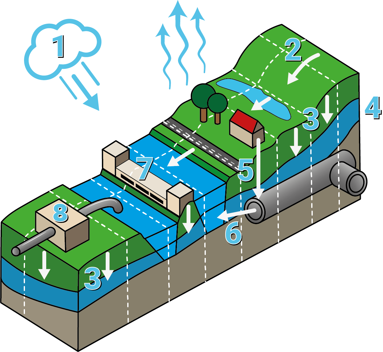
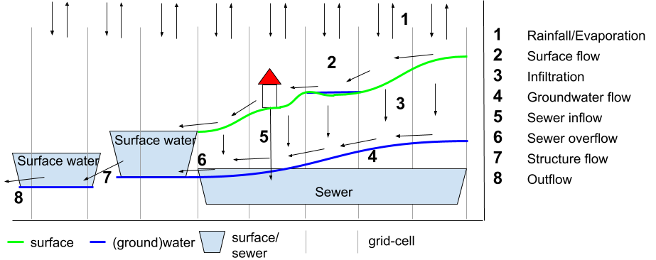
Rainfall/Evaporation
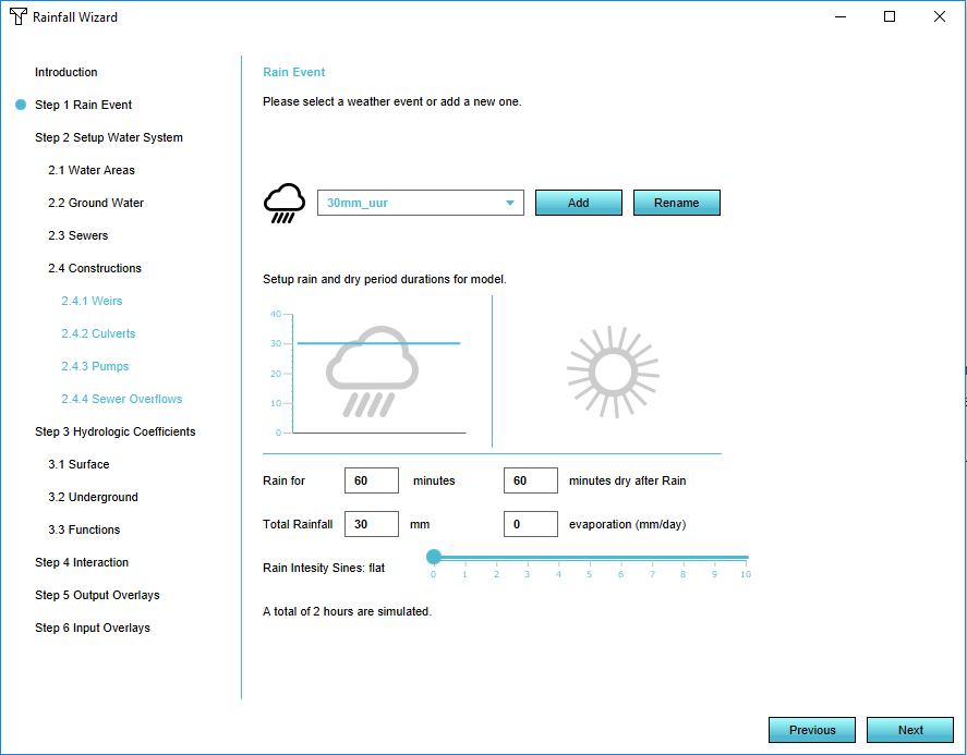
Rainfall can be specified uniform for the entire computational grid, using the rainfall overlay wizard. The following can be specified:
- amount: the total amount of rainfall over time (mm)
- duration: the length of the rainfall event
- sines: the amount of peaks (represented by sines) in the rainfall event
Potential evapotranspiration is computed with the following equation:
ETpot = ETc x Kc
Where ETc is the reference potential evapotranspiration, filled in the weather tab of the rainfall overlay. The potential evaporation, computed from meteorological parameters and representative for a reference surface. According to the FAO [1]:
The reference surface is a hypothetical grass reference crop with an assumed crop height of 0.12 m, a fixed surface resistance of 70 s m-1 and an albedo of 0.23. The reference surface closely resembles an extensive surface of green, well-watered grass of uniform height, actively growing and completely shading the ground. The fixed surface resistance of 70 s m-1 implies a moderately dry soil surface resulting from about a weekly irrigation frequency.
Kc is the crop coefficient; a multiplication factor on ETc for converting to potential evapotranspiration. Kc is related to the terrain type specified for the respective cell. If the cell is inundated the value for open water is used.
No unsaturated zone description is available. Therefore evaporation can only take place from the surface and is limited to the total amount of water available on the surface and/or being infiltrated in the sub-soil.
Surface flow
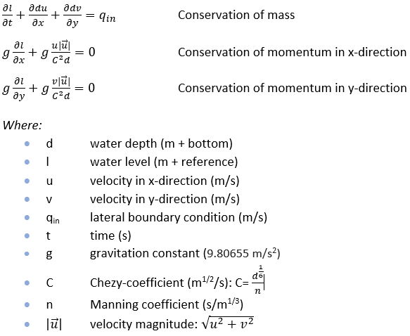
Surface flow is computed, using the diffusive wave approximation in a simple explicit computation scheme:
The basic assumptions behind the implementation of the surface flow computation scheme are:
- Flow velocities are small
- Flow volumes are small
- From (1) and (2) follows: momentum (momentum = mass(volume) * velocity) is small
- And from the above it is assumed all momentum is locally generated by pressure, gravity and friction forces. Momentum on cell XY, has no impact on flow in adjacent cells.
The numerical scheme as been tested on the benchmark of the Dutch STOWA (STOWA, 2017)
Infiltration
Water stored on the surface, not added to sewer, building storage or evaporated can infiltrate in the subsoil. A cells infiltration capacity is assumed by:
I = min(Ib,Isurf,Kv)
where:
- I is a cells infiltration capacity (m/day)
- Ib is the GROUND_INFILTRATION_MD attribute assigned to the building on the specific cell.
- Isurf is the GROUND_INFILTRATION_MD attribute assigned to the surface of a specific cell.
- Kv is the GROUND_INFILTRATION_MD attribute assigned to the underground of a specific cell. This value should be interpreted as the vertical conductivity (Kv) of the sub-soil.
Groundwater flow
Groundwater is represented by one layer (the phreatic groundwater layer). Groundwater flow is computed by Darcy's law:
Q=Kd∙i
where:
- Q = the groundwater flow from one cell to its adjacent cells
- Kd = the horizontal hydraulic conductivity of the soil * the depth of the groundwater layer (m3/s). Currently the value is represented by the VH_INFILTRATION_FACTOR (attribute of the rainfall overlay), multiplied by the infiltration capacity of the underground layer
- i is the groundwater slope
Sewer inflow
Water stored on the surface can flow into the sewer district every timestep, until the sewer storage in the sewer district is depleted. This is described as:
Qsewer = min(Ssewer, Ssurface)
where:
- Qsewer = sewer inflow
- Ssewer = sewer storage capacity
- Ssurface = amount of water available on the surface
Sewer overflow
A sewer overflow connects a sewer area to a water level area. An overflow exists in the Engine as a construction. Only if the water level in the water connected water level area is lower than the overflow crest level, water can discharge towards the water level area. The overflow discharge (Q) is limited by the maximum overflow capacity only.
Structure flow
Hydraulic structures exist as a construction connecting two water level areas or a sewer district to a water level area.
Weirs
A weir connects two water level areas. A weir exists in the Engine as a construction. Weir flow (Q) is depending on the upstream water level (Hus), using the formula for free weir flow:
Q= 1.7 x M x WIDTH x (Hus-Hcrest)^(N)
Culverts
A culvert connects two water level areas. A culvert exists in the Engine as a construction. The culvert flow (Q) is imited by the maximum flow capacity only. The direction of flow is towards the water level area with the lowest water level.
Pumps
A pump connects two water level areas. A pump exists in the Engine as a construction. The pump flow (Q) is limited by the maximum pump capacity only. The direction of flow is towards the water level area with the highest water level.
Outflow
In a water area a stationary outflow can be specified (m3/s). This outflow is extracted from the volume available in water cells if available.
General Tab
Calculation Preference
Here you can manipulate the computation time step by choosing between the option SPEED, AVERAGE and ACCURACY. The computational timesteps will be set according to the Courant criterion:
Δt = Δx /umax
where:
- Δt = computational timestep
- Δx = grid cell size
- umax = max velocity, assumed 2.5 (SPEED), 5 (AVERAGE) and 10 (ACCURACY) m&sub3;/s respectively
Grid cell size
The Tygron Engine computes flow equations over a rectangular cartesian grid, the grid cell size can be set in the General Tab of the Rainfall Overlay. Note: if you choose a smaller grid cell size, both the amount of time steps (see Calculation Preference) and amount of computational cells increase.
Export GeoTiff & Water Balance
You can export the current result-type as GeoTiff and a waterbalance as Microsoft Excel file.
Debug Info
General info
The debug info contains the following information:
- Rain: the amount of rainfall (mm) in the duration of the rainfall event (hours)
- Total Simulation: the simulation period (hours)
- Cells: The dimensions of the simulation: the amount of computational cells and the amount of time steps (cycles)
- Weir flow: the amount of water flown over weirs during simulation (m3)
- Sewer overflow: the amount of water flown over sewer overflows during simulation (m3)
- GPU time: the computation time on GPU (seconds)
- Max Courant avg: the maximum courant numbers reached during the simulation
Water balance
The water balance is made up of the following components:
- Land surface: amount of water on the land surface after simulation (m3)
- Water surface: amount of water stored on water cells after simulation (m3)
- Building storage: amount of water stored in building storage (m3)
- Sewer storage: amount of water stored in sewers after simulation (m3)
- Underground storage: amount of water stored in the sub-soil after simulation (m3)
- Evaporated: amount of water evaporated after simulation (m3)
- Outlet: amount of water extracted from the model during the simulation via outlets of water areas or sewer pumps (m3).
Overlay Keys
Keys referring to area attributes
| Attribute | Unit | Description |
|---|---|---|
| Water Level | m + datum | initial water level, relative to datum, for all water cells in a water area |
| Outlet | m3/s | water abstraction for all water cells in a water area |
| Sewer Storage | m | available storage in sewers at the start of simulation in a sewer area |
| Sewer Pump Speed | m3/s | sewer water abstraction for all cells in a sewer area |
Keys referring to structures (building attributes)
| Attribute | Unit | Description |
|---|---|---|
| Weir Height | m + datum | weir crest level |
| Weir Width | m | the width of the crest of a weir |
| Weir Coefficient | linear weir coefficient for accounting discharge & contraction losses | |
| Culvert Speed | m3/s | the discharge capacity of a culvert |
| Pump Speed | m3/s | the capacity of a pump |
| Sewer Overflow Height | m + datum | the height of a crest of a sewer overflow |
| Sewer Overflow Speed | m3/s | the discharge capacity of a sewer overflow |
Overlay Attributes
| Attribute | Unit | Description |
|---|---|---|
| ALLOWED_WATER_INCREASE_M | m | increment by which the water level on a water cell is allowed to increase before the depth is shown in the water stress result type |
| IMPACT FLOOD_THRESHOLD_M | m | maximum waterdepth around a building where after the building is assumed impacted |
| MIN_SLOPE | slope whereunder the pressure slope is assumed 0 | |
| SEWER_OVERFLOW_THRESHOLD | fraction of storage whereafter sewer overflows take place | |
| SIMULATION_TIME_HOURS | hours | simulation time |
Including subsidence
For the calculation of the effects of a severe rainfall, effects of subsidence can be included, such as the recalculated water levels and the changed ground levels. For now, ground water levels affected by the subsidence are not included.
- Add the subsidence overlay. Take note of when to use and how to configure the subsidence overlay.
- In the right panel, select the "Keys" tab
- Select the "Area attribute: output level (m)". Choose a new attribute, for example the WATER_LEVEL_OUTPUT attribute, to write the new water levels to.
- In the Rainfall overlay in the right panel, select the "Keys" tab.
- Choose the overlay for the subsidence model you want to use in the "Include Subsidence" form.
- Also select the newly created attribute containing the water levels in the "Area Attribute: Water Level (m)" form.
- Go to the "General" tab and recalculate the grid.
Be careful not to write the new water levels calculated in the subsidence overlay to the already existing water level attribute, otherwise the subsidence model will be recalculated with incorrect values when refreshing this overlay.
You can play around with the results of the two overlays and compare, for example, two rainfall overlays where one overlay takes the effects of a subsidence model into account and the other overlay shows results without these effects.
