Breach model (Water Overlay): Difference between revisions
No edit summary |
|||
| (34 intermediate revisions by 2 users not shown) | |||
| Line 1: | Line 1: | ||
A Breach can be defined as an area and is identified via the [[Breach_height_(Water_Overlay)|BREACH_HEIGHT]] | A [[Breach (Water Overlay)|Breach]] can be defined as an area and is identified via the [[Breach_height_(Water_Overlay)|BREACH_HEIGHT]] [[key]]. Water flowing through the breach originates from a body of water. This body of water can be defined as an input area in the project or a conceptual external water body existing outside the project area. Water can flow through the breach from the input water body to the defined Breach area, and vice versa. | ||
The breach is simulated as a generic [[Breach_flow_formula_(Water_Overlay)|weir]] with breach characteristics that models the energy loss, the weir input/output is dynamically mapped onto the 2D grid cells. Using the [[Breach_growth_formula_(Water_Overlay)|Verheij–van der Knaap]] method the breach can also grow over time from phase one deepening to phase two widening | The breach is simulated as a generic [[Breach_flow_formula_(Water_Overlay)|weir]] with breach characteristics that models the energy loss, the weir input/output is dynamically mapped onto the 2D grid cells. Using the [[Breach_growth_formula_(Water_Overlay)|Verheij–van der Knaap]] method the breach can also grow over time from phase one deepening to phase two widening. | ||
===Breach placement=== | |||
A breach is defined using an [[Area]] that has the [[key]] [[Breach height (Water Overlay)|BREACH_HEIGHT]] set. Its base are is defined by the geometry of the breach area. The breach is also given a starting [[breach width (Water Overlay)|width]]. Optionally it can also be given an [[Breach angle (Water Overlay)|angle]], which is used in the flow formula and in placing the downstream level measurement point. | |||
The images below show two different setups. Note that the configuration of input and level measuring can also be done in a different combination, not only the two shown below. | |||
== | <gallery widths=500px heights=300px> | ||
File:breach-side6.png|Side View of a Breach with a [[Breach height (Water Overlay)|height]], a [[Breach input area (Water Overlay)]] with a [[Water level (Water Overlay)|water level]], a [[Breach (Water Overlay)|breach]] as an [[Area|area]] where the water is released when it conceptually passes the breach and an inner level measurement point which calculates the downstream (inner) water level. | |||
File:breach-top5.png|Top View of a Breach with a [[Breach width (Water Overlay)|width]] and a [[Breach angle (Water Overlay)|direction]], a [[Breach measurement distance m (Water Overlay)|point of measurement at a distance]] and an [[Breach input area (Water Overlay)|input area]] within a [[Water area (Water Overlay)|Water Area]]. | |||
</gallery> | |||
<gallery widths=500px heights=300px> | |||
File:breach-side_ext.png|Side View of an alternative setup with an external water body defined by an [[External water level (Water Overlay)|external water]] and [[External surface level (Water Overlay)|surface level]] from which the water originates, a [[Breach (Water Overlay)|breach]] as an [[Area|area]] with a [[Breach height (Water Overlay)|height]], where the water is released when it conceptually passes the breach and a [[Breach level area (Water Overlay)|Breach level area]] which calculates the downstream (inner) water level. | |||
File:breach-top-ext.png|thumb|left|500px|Top View of an alternative setup with a Breach with a [[Breach width (Water Overlay)|width]] and a [[Breach angle (Water Overlay)|direction]], a [[Breach level area (Water Overlay)|Breach level area]] and an [[External area (Water Overlay)|external area]] which is conceptually located outside the project area.</gallery> | |||
==Breach input== | |||
The origin of the water flowing through the breach can be done in two ways: | |||
*a source outside the project, defined using an [[External area (Water Overlay)|external area]], [[External water level (Water Overlay)|external water level]] and [[External surface level (Water Overlay)|external surface level]]. | |||
*a source within the project, defined [[Breach input area (Water Overlay)|input area]]; | |||
===External source=== | |||
When using an external source, it is quite easy to set up. This setup is useful when there is a large body of water that does not fit within your projects bounds. It is currently not possible to configure a manually changing external water level during simulation; the water level lowers or rises only based on the amount of water that has flown through the breach. Each individual breach uses its own external water body; these are not shared among breaches. | |||
===Input Area=== | |||
When you want to simulate a breach with a body of water situated within your project bounds, you can also use [[Breach input area (Water Overlay)|input area]]. An input area is expected to be situated in a [[Water area (Water Overlay)|Water Area]]. Input areas are not allowed to overlap. However, they are allowed to be situated within the same [[Water area (Water Overlay)|Water Area]]. | |||
Each Breach simulation step the water level will be determined for the input are and the breach area and used to calculate the flow. The calculated amount is then removed from the input area and the water levels are recalculated for the input area. During the water simulation steps, water can flow into the input area according to the [[Surface model (Water Overlay)|surface water model calculations]]. | |||
* | ==Breach flow== | ||
The amount of water that flows through a breach is calculated each timestep based on: | |||
* The calculated water levels on both sides, based on the configuration mentioned in the previous section. | |||
* The parameters of the breach; | |||
** [[Breach_height_(Water_Overlay)|Breach height]]; as a single value or a value changing over time, allowing you this simulate the breach vertical growth. | |||
** [[Breach_width_(Water_Overlay)|Breach width]]; as a starting width. Can grow over time according to the [[Breach_growth_formula_(Water_Overlay)|Verheij–van der Knaap growth formula]]. | |||
** [[Breach_speed_(Water_Overlay)|Breach critical speed]], a parameter in the flow formula. Its value is related to the shape of the breach, similar to the [[Weir coefficient (Water Overlay)|weir coefficient]]. | |||
** [[Breach_angle_(Water_Overlay)|Breach angle]], used to give direction to the moved volume of water. | |||
==Breach flow direction== | |||
Water flowing through the breach will flow in the direction defined by the [[Breach_angle_(Water_Overlay)|BREACH_ANGLE]] attribute, regardless of whether the water flowed onto the breach from elsewhere in the water model, or from the simulated external water body. When no [[Breach_angle_(Water_Overlay)|BREACH_ANGLE]] is defined, water can flow in any direction. Adding this attribute with also convert the breach advection speed (m/s) into the 2D cell of the breach area. It is recommended to always use this attribute for optimal flow. | |||
<gallery widths=500px heights=300px> | |||
File:breach-active.png|[[Flooding Overlay]] [[Base types result type (Water Overlay)|base type result]] showing the active an inactive part of the breach. | |||
File:breach-direction.png|[[Flooding Overlay]] [[Surface_last_direction_result_type_(Water_Overlay)|surface direction result]] showing the direction on the active and surrounding area around the breach. | |||
</gallery> | |||
==Breach width growth== | |||
* The breach can grow over time, based on its initial [[Breach width (Water Overlay)|width]], [[Breach speed (Water Overlay)|critical speed]] and inner and outer water level, for more details see [[Breach growth formula (Water Overlay)|Verheij–van der Knaap growth formula]]. | |||
* If a [[Breach width (Water Overlay)|BREACH_WIDTH]] attribute is defined, the breach's polygon is intersected with a circle emanating from the center-point of the polygon. It is only in that intersection, called "active", that water will flow in from the input area. The radius of the circle defining the intersection will expand as the breach grows over time. | |||
* If no width is defined, the width is assumed to be very large, using the full Breach area polygon. | * If no width is defined, the width is assumed to be very large, using the full Breach area polygon. | ||
* With larger breaches the water level inside the breach area can become turbulent. Therefor the inner water level (used for breach growth) is measured at a distance defined in [[Breach measurement distance m (Water Overlay)|BREACH_MEASUREMENT_DISTANCE_M]] behind the breach area when an [[Breach angle (Water Overlay)|BREACH_ANGLE]] is provided. | |||
* The [[ | * Instead of using an input area you can also define a fictitious external area, this can represent a larger water body outside the project area, e.g. a part of a sea. The external area also has it's own [[External surface level (Water Overlay)|Surface level]], [[External water level (Water Overlay)|Water level]] and [[External area (Water Overlay)|Area]]. | ||
* If no [[Breach speed (Water Overlay)|BREACH_SPEED]] attribute is defined, the active breach will never grow. | |||
{{article end | {{article end | ||
|notes= | |notes= | ||
* The elevation model covered by the entire breach area is lowered to at least the minimum height defined by its [[ | * The elevation model covered by the entire breach area is lowered to at least the minimum height defined by its [[Breach height (Water Overlay)|BREACH HEIGHT]] attribute. This is to prevent the terrain height from interfering with the flow. | ||
* When using breach growth the inner water level is computed from the average value in the active breach area. For optimal flow simulation it is therefor recommended to place the breach area just behind the levee on a flat space. | * When using breach growth the inner water level is computed from the average value in the active breach area. For optimal flow simulation it is therefor recommended to place the breach area just behind the levee on a flat space. | ||
* Water on a breach area is automatically spread across the entire active breach area equally. | * Water on a breach area is automatically spread across the entire active breach area equally. | ||
* The inner/outer water levels and breach width are visualized per timeframe on the breach object in the 3D map, these can be very useful to see how the breach is progressing. | * The inner/outer water levels and breach width are visualized per timeframe on the breach object in the 3D map, these can be very useful to see how the breach is progressing. | ||
* The [[ | * The [[Base types result type (Water Overlay)|Base Types Result]] child overlay can be used to see which part of entire the breach area is considered "active". Breach growth can be seen when checking multiple timeframes. | ||
* You can also optionally change the default breach weir coefficient to model energy loss by adding a [[ | * You can also optionally change the default breach weir coefficient to model energy loss by adding a [[Weir coefficient (Water Overlay)|WEIR_COEFFICIENT]] attribute to the Breach area. | ||
* When the water level of in the input area drops over time the flow can also reverse, flowing back into the e.g. the river/sea. | * When the water level of in the input area drops over time the flow can also reverse, flowing back into the e.g. the river/sea. | ||
|seealso= | |seealso= | ||
*[[Breach (Water Overlay)]] | * [[Breach (Water Overlay)]] | ||
*[[Breach flow formula (Water Overlay)]] | * [[Breach flow formula (Water Overlay)]] | ||
*[[Breach growth formula (Water Overlay)]] | * [[Breach growth formula (Water Overlay)]] | ||
}} | }} | ||
{{WaterOverlay formula nav}} | {{WaterOverlay formula nav}} | ||
Latest revision as of 14:36, 26 January 2023
A Breach can be defined as an area and is identified via the BREACH_HEIGHT key. Water flowing through the breach originates from a body of water. This body of water can be defined as an input area in the project or a conceptual external water body existing outside the project area. Water can flow through the breach from the input water body to the defined Breach area, and vice versa.
The breach is simulated as a generic weir with breach characteristics that models the energy loss, the weir input/output is dynamically mapped onto the 2D grid cells. Using the Verheij–van der Knaap method the breach can also grow over time from phase one deepening to phase two widening.
Breach placement
A breach is defined using an Area that has the key BREACH_HEIGHT set. Its base are is defined by the geometry of the breach area. The breach is also given a starting width. Optionally it can also be given an angle, which is used in the flow formula and in placing the downstream level measurement point.
The images below show two different setups. Note that the configuration of input and level measuring can also be done in a different combination, not only the two shown below.
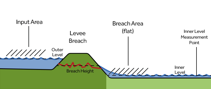
Side View of a Breach with a height, a Breach input area (Water Overlay) with a water level, a breach as an area where the water is released when it conceptually passes the breach and an inner level measurement point which calculates the downstream (inner) water level.
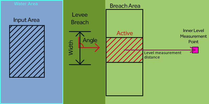
Top View of a Breach with a width and a direction, a point of measurement at a distance and an input area within a Water Area.


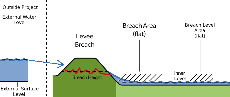
Side View of an alternative setup with an external water body defined by an external water and surface level from which the water originates, a breach as an area with a height, where the water is released when it conceptually passes the breach and a Breach level area which calculates the downstream (inner) water level.
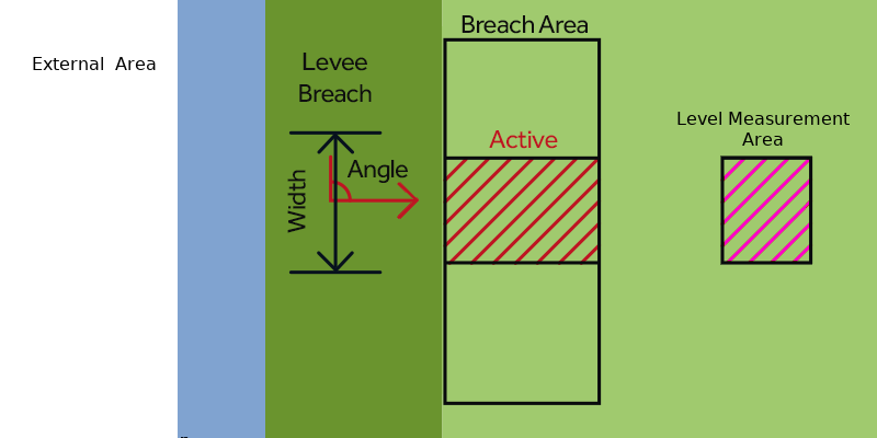
Top View of an alternative setup with a Breach with a width and a direction, a Breach level area and an external area which is conceptually located outside the project area.


Breach input
The origin of the water flowing through the breach can be done in two ways:
- a source outside the project, defined using an external area, external water level and external surface level.
- a source within the project, defined input area;
External source
When using an external source, it is quite easy to set up. This setup is useful when there is a large body of water that does not fit within your projects bounds. It is currently not possible to configure a manually changing external water level during simulation; the water level lowers or rises only based on the amount of water that has flown through the breach. Each individual breach uses its own external water body; these are not shared among breaches.
Input Area
When you want to simulate a breach with a body of water situated within your project bounds, you can also use input area. An input area is expected to be situated in a Water Area. Input areas are not allowed to overlap. However, they are allowed to be situated within the same Water Area.
Each Breach simulation step the water level will be determined for the input are and the breach area and used to calculate the flow. The calculated amount is then removed from the input area and the water levels are recalculated for the input area. During the water simulation steps, water can flow into the input area according to the surface water model calculations.
Breach flow
The amount of water that flows through a breach is calculated each timestep based on:
- The calculated water levels on both sides, based on the configuration mentioned in the previous section.
- The parameters of the breach;
- Breach height; as a single value or a value changing over time, allowing you this simulate the breach vertical growth.
- Breach width; as a starting width. Can grow over time according to the Verheij–van der Knaap growth formula.
- Breach critical speed, a parameter in the flow formula. Its value is related to the shape of the breach, similar to the weir coefficient.
- Breach angle, used to give direction to the moved volume of water.
Breach flow direction
Water flowing through the breach will flow in the direction defined by the BREACH_ANGLE attribute, regardless of whether the water flowed onto the breach from elsewhere in the water model, or from the simulated external water body. When no BREACH_ANGLE is defined, water can flow in any direction. Adding this attribute with also convert the breach advection speed (m/s) into the 2D cell of the breach area. It is recommended to always use this attribute for optimal flow.
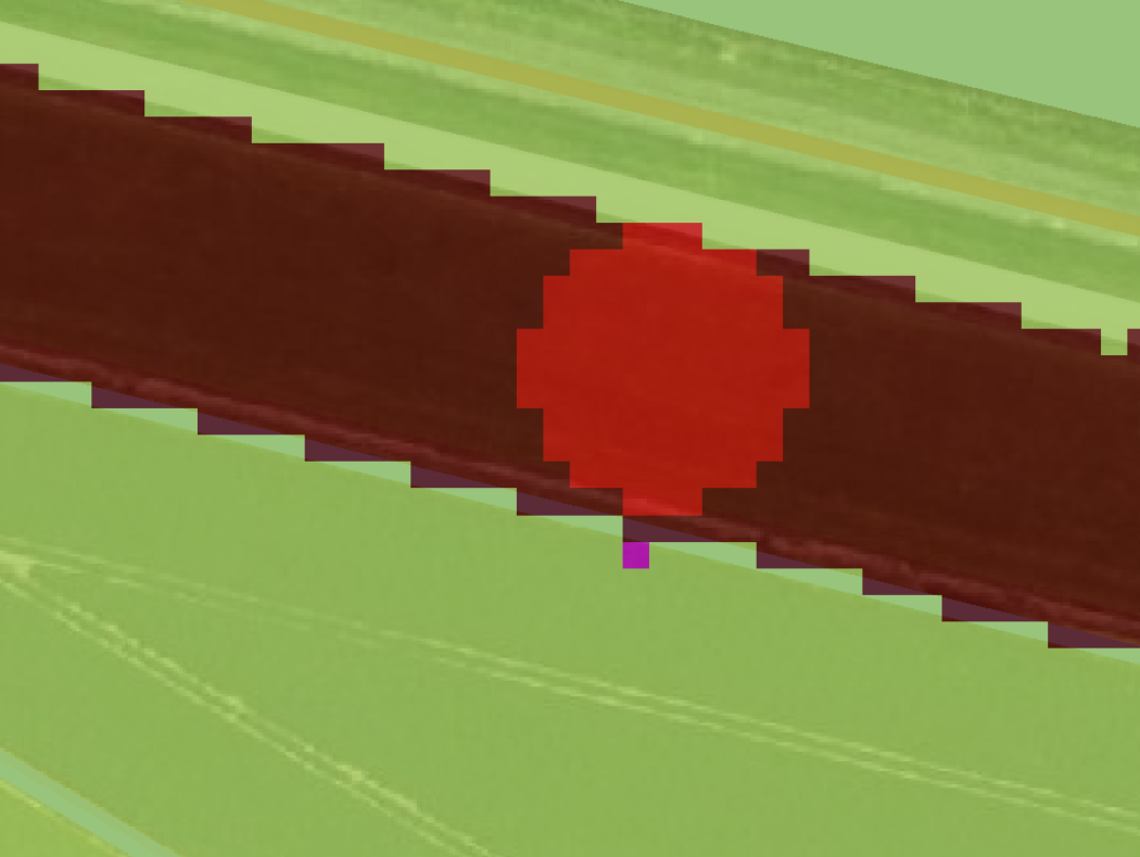
Flooding Overlay base type result showing the active an inactive part of the breach.
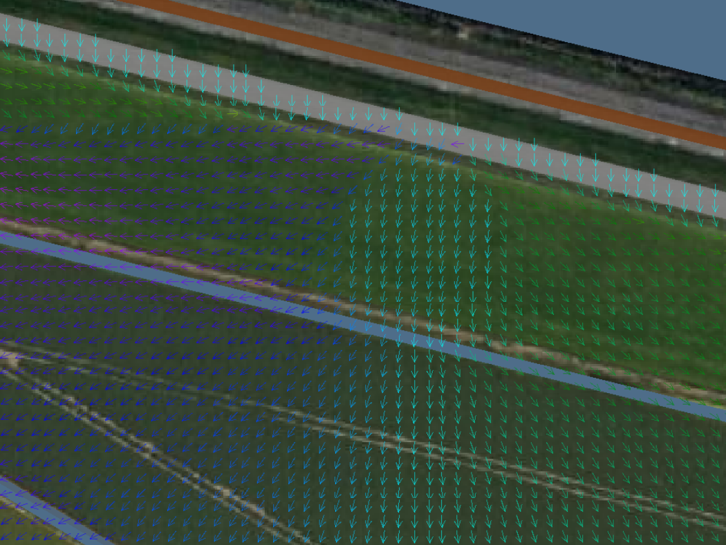
Flooding Overlay surface direction result showing the direction on the active and surrounding area around the breach.


Breach width growth
- The breach can grow over time, based on its initial width, critical speed and inner and outer water level, for more details see Verheij–van der Knaap growth formula.
- If a BREACH_WIDTH attribute is defined, the breach's polygon is intersected with a circle emanating from the center-point of the polygon. It is only in that intersection, called "active", that water will flow in from the input area. The radius of the circle defining the intersection will expand as the breach grows over time.
- If no width is defined, the width is assumed to be very large, using the full Breach area polygon.
- With larger breaches the water level inside the breach area can become turbulent. Therefor the inner water level (used for breach growth) is measured at a distance defined in BREACH_MEASUREMENT_DISTANCE_M behind the breach area when an BREACH_ANGLE is provided.
- Instead of using an input area you can also define a fictitious external area, this can represent a larger water body outside the project area, e.g. a part of a sea. The external area also has it's own Surface level, Water level and Area.
- If no BREACH_SPEED attribute is defined, the active breach will never grow.
Notes
- The elevation model covered by the entire breach area is lowered to at least the minimum height defined by its BREACH HEIGHT attribute. This is to prevent the terrain height from interfering with the flow.
- When using breach growth the inner water level is computed from the average value in the active breach area. For optimal flow simulation it is therefor recommended to place the breach area just behind the levee on a flat space.
- Water on a breach area is automatically spread across the entire active breach area equally.
- The inner/outer water levels and breach width are visualized per timeframe on the breach object in the 3D map, these can be very useful to see how the breach is progressing.
- The Base Types Result child overlay can be used to see which part of entire the breach area is considered "active". Breach growth can be seen when checking multiple timeframes.
- You can also optionally change the default breach weir coefficient to model energy loss by adding a WEIR_COEFFICIENT attribute to the Breach area.
- When the water level of in the input area drops over time the flow can also reverse, flowing back into the e.g. the river/sea.
See also


- Models
- Surface • Ground • Rain • Evaporation • Infiltration • Elevation • Breach • Sewer • Storage • Tracer flow • Border • Order
- Model formulas
- Timestep • Season • Surface water level • Groundwater level
- Flow formulas
- Surface flow • Surface infiltration • Ground flow • Ground infiltration • Surface evaporation • Ground evaporation • Ground bottom flow
- Hydraulic structure formulas
- Culvert • Weir • Breach growth • Breach flow • Pump • Sewer Overflow • Inlet • Drainage
- Related