How to create a parametric design: Difference between revisions
Jump to navigation
Jump to search

No edit summary |
No edit summary |
||
| Line 9: | Line 9: | ||
| Click on Generate Design. | | Click on Generate Design. | ||
| Verify that the selections in the [[3D world]] and the information in the [[Chart_(Parametric_Design)|pie chart]] look like the desired result. If not, tweak the parameters (in the Design tab) further. | | Verify that the selections in the [[3D world]] and the information in the [[Chart_(Parametric_Design)|pie chart]] look like the desired result. If not, tweak the parameters (in the Design tab) further. | ||
| Either apply the design to start a [[Test Run]] | | Either apply the design to start a [[Test Run]], click on Save to Current to construct the Design in the [[Current Situation]] or save the design as a [[Measure]]. | ||
| Verify that the result is correct. If not, revert the application by clicking on Revert last Design and tweak the configuration further (this step is not possible when having the design saved to Current). | | Verify that the result is correct. If not, revert the application by clicking on Revert last Design and tweak the configuration further (this step is not possible when having the design saved to Current). | ||
}} | }} | ||
| Line 31: | Line 31: | ||
==See also== | ==See also== | ||
* [[Parametric Design]] | * [[Parametric Design]] | ||
* [[How to save a parametric design as a measure]] | |||
<!--* [[How to create an urban area using parametric design]] | <!--* [[How to create an urban area using parametric design]] | ||
* [[How to create an area of trees using parametric design]]--> | * [[How to create an area of trees using parametric design]]--> | ||
Revision as of 10:59, 4 March 2021
Editor → Future Design (Ribbon tab) → Parametric (Ribbon bar) → The Parametric Design to edit (Left panel)
How to create and use a Parametric design:
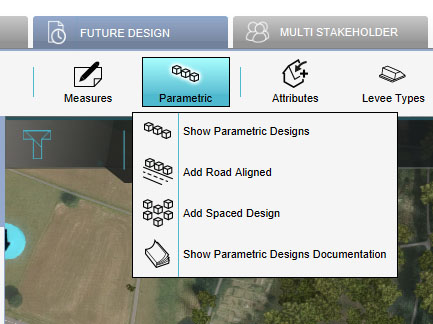
- Click on the Future Design tab
- Hover over the Parametric Design button and choose Add road aligned or Add spaced design. In the left panel a new Design is added.
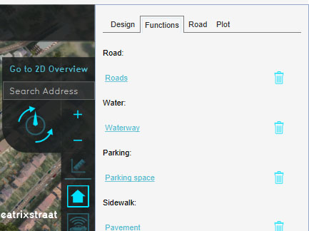
- Select the Design in the left panel and click on the Functions tab in the right panel. Select the desired functions. These will be type of Constructions placed by the design.
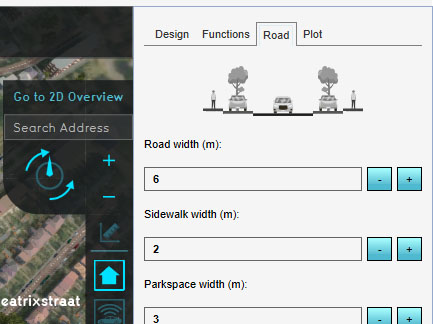
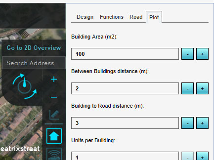
- Adjust the parameters in the Road and Plot tabs.
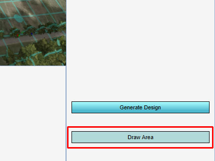
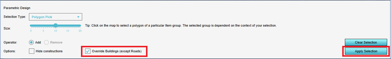
- Click on the Draw Area button in the right bottom corner. In the Bottom panel, the option for Override buildings is automatically checked. If you would not like to remove existing Buildings to make place for the new design, uncheck this option. Then draw the area for the design in the 3D world and choose 'apply selection'.
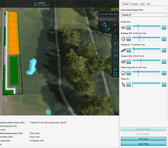
- Then adjust the parameters in the Design tab.
- Click on Generate Design.
- Verify that the selections in the 3D world and the information in the pie chart look like the desired result. If not, tweak the parameters (in the Design tab) further.
- Either apply the design to start a Test Run, click on Save to Current to construct the Design in the Current Situation or save the design as a Measure.
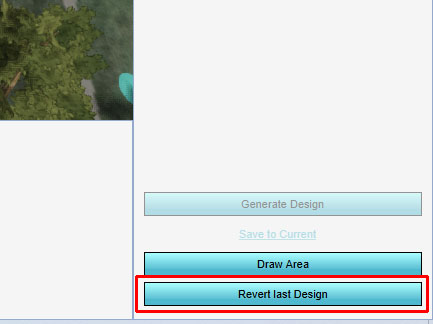
- Verify that the result is correct. If not, revert the application by clicking on Revert last Design and tweak the configuration further (this step is not possible when having the design saved to Current).


Notes
- Save to current: a test run is not started. Instead it is applied to the Current Situation. This method is not easily reversed.
- Tip: use the Polygon pick selection tool to draw the area for the design.