Troubleshoot: Configured lower threshold for pump is not reached
A Pump is often configured with a lower water level threshold, such that it pumps away water from a water level area until this water level is reached. Additionally, it can be configured with a maximum pump speed, using PUMP_Q.
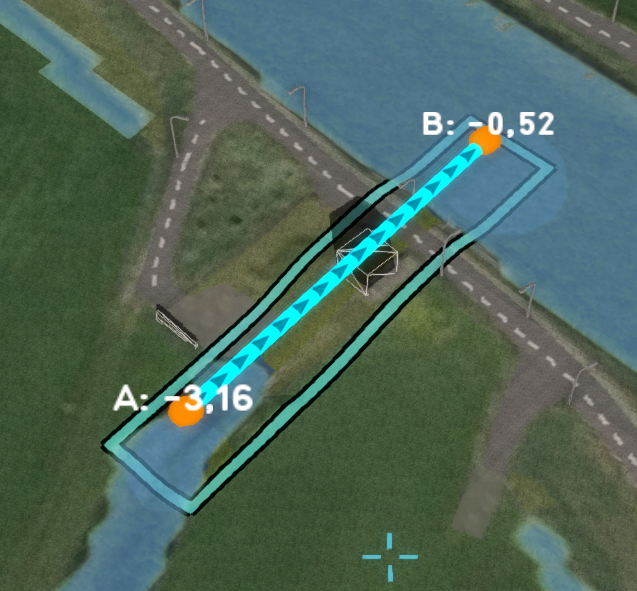
The pump is often originally drawn as a single line or rectangle, connecting the lower water level area with the higher water level area, as can be seen in the first image below.
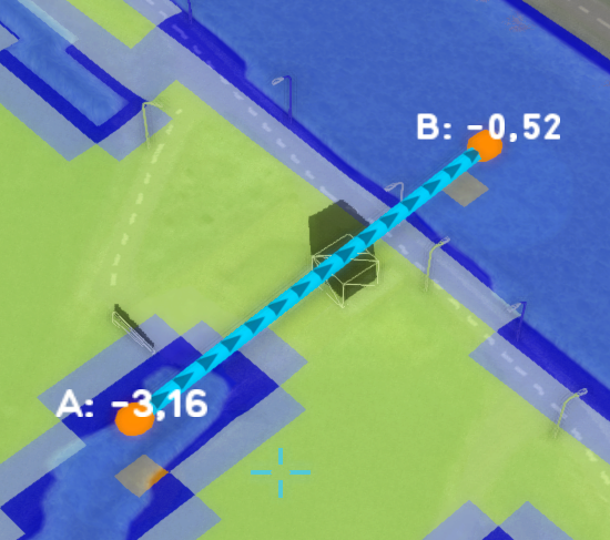
By default, a pump is not configured as an area. This means that it only subtracts water from a single point, and disposes the water on an other single point. These end points are based on a internal line generated for the polygon configured for the pump, which is visualized in the first image. In the second image you can see the single cells that are used in by the water model calculations, indicated by the orange color.
Since a cell can hold only a certain amount of water at a given time, grid cell size times water height on the surface, a pump can also only subtract that much water from this cell. This means that a pump's maximum subtraction amount is also limited by the amount of water on this endpoint cells. This will obviously lead to capacity problems, where the desired lower water level is never reached.
To solve this issue, you can do the following:
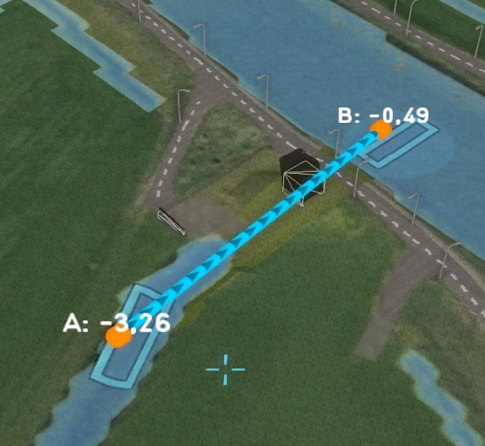
- Configure the pump to use input areas, using the Pump area option.
- Provide the pump with two clearly separated areas, one for the lower and one for the upper water level area. Also try to draw these areas as much in the deeper parts of the waterway as possible.
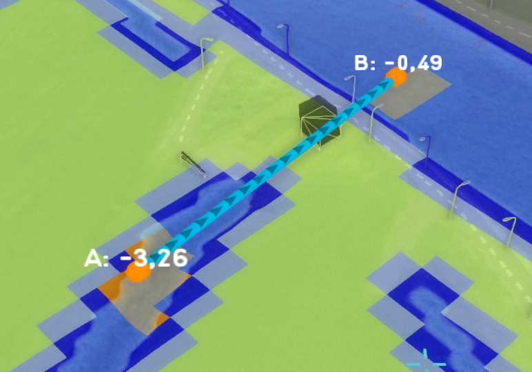
You now have more control over which cells the pump will subtract water from, and that it will have enough. Depending on the maximum capacity of the pump, the area can be made larger or smaller. See also the third and fourth images. Notice that the lower water threshold is now much closer (3.26 ~ 3.28 depending on the rainfall) to what is configured (-3.3 meters) compared to the original situation (3.16).
-
A pump consisting of one line area, with one entry point for the lower and one for the upper Water level areas. It only used a single cell to subtract water from, which might not be enough.
-
The base type overlay indicating that only one cell is used to subtract water from.
-
A pump consisting of two separate areas, one for the lower and one for the upper Water level areas. It uses a lower level threshold and requires multiple grid cells to subtract enough water. It is configured as a PUMP_AREA.
-
The base type overlay indicating that this pump now uses multiple cells to subtract water from.


