Weir height test case (Water Module)
This page contains information on what ways a weir's height can be configured using a test case. It also shows what direct output you can inspect from a weir. Finally, several variants are also explored.
Description
This test case consists of several weirs situated in a waterway, with each weir having different properties. All weirs are part of the same Water Overlay's simulation. There is no rainfall in this test case. Instead water flow is provided by inlets and outlets, which can be set up either variable or constant.

Boundary and initial conditions
- Waterways with weirs in the middle, separating two water areas.
- One inlet per waterway providing an influx of water, situated in the water area on the left.
- One outlet per waterway providing an outflux of water, situated in the water area on the right.
Parameter values
- Manning’s n: 0.03 (uniform)
- Model grid resolution: 1m
Technical setup
Waterways
Four waterways with a water depth of 2m and an angle of repose of 35 degrees, drawn with the following polygons:
- [187.0, -249.288], [418.0, -256.288]
- [413.0, -333.288], [189.0, -326.288]
- [194.0, -375.287], [411.0, -382.287]
- [404.0, -447.430], [194.0, -440.430]
Water Areas
Two areas divide the water ways into two sections:
- Water area (left)
- Rectangle shape: [301.0, -226.466], [158.884, -464.466]
- WATER_LEVEL = 0.0;
- Water area (right)
- Rectangle shape: [424.884, -226.466], [301.0, -464.466]
- WATER_LEVEL = 0.0;
Inlets
- Inlet (Constant):
- Rectangle shape: [189.82, -254.350], [202.08, -251.510]
- INLET_AREA = 1.0;
- INLET_Q = 1.0;
- LOWER_THRESHOLD = -10 000 (inactive);
- UPPER_THRESHOLD = -10 000 (inactive);
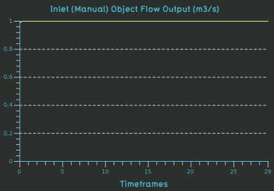
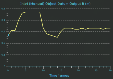
- Inlet (Manual)
- Rectangle shape: [192.116, -331.225], [199.453, -328.390]
- INLET_AREA = 1.0;
- INLET_Q = 1.0;
- LOWER_THRESHOLD = -10 000 (inactive);
- UPPER_THRESHOLD = -10 000 (inactive);
- Inlet (Adjusting)

- Rectangle shape: [197.019, -444.276], [204.623, -441.738]
- INLET_AREA = 1.0;
- INLET_Q = [0, 1, 600, 1, 900, 1.5, 1200, 1.5, 1800, 1.5, 2400, 1, 3600, 1];
- LOWER_THRESHOLD = -10 000 (inactive);
- UPPER_THRESHOLD = -10 000 (inactive);
Outlets
Each outlet is set up with the following attributes to remove the water that passed through the weir:
- INLET_AREA = 1.0;
- INLET_Q = 0;
- UPPER_THRESHOLD = -0.5;
The outlets are situated at:
- Outlet (Constant):
- Rectangle shape: [414.554, -250.689] , [396.786, -253.873]
- Outlet (Manual):
- Rectangle shape: [410.115, -327.753] , [ 393.13, -330.9620 ]
- Outlet (Adjusting):
- Rectangle shape: [ 401.072, -442.541 ], [ 383.968, -445.520 ]
Weirs
Each weir is setup using a rectangular shape, and direction angle and a weir height and width:
- WEIR_ANGLE = 270 degrees;
- WEIR_HEIGHT = 0 m;
- WEIR_WIDTH = 5 m;
Weir specific:
- Weir (Constant)
- Rectangular shape: [ 299.593, -248.328 ] , [ 302.229, -257.983 ]
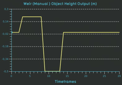
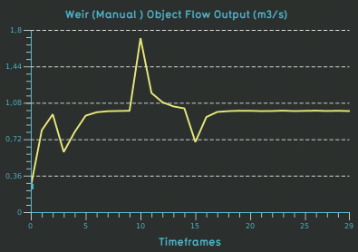
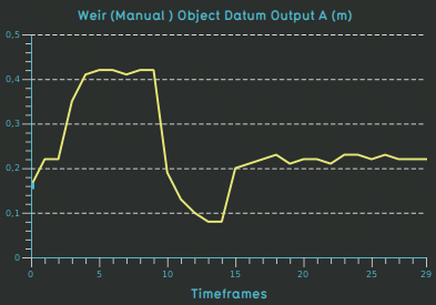
- Weir (Manual)

- Rectangular shape: [ 298.675, -324.174 ] , [ 301.613, -335.662 ]
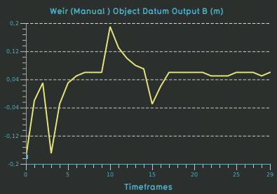
- WEIR_HEIGHT = [ 0 0 600 0.2 1200 0.2 1500 0.2 1800 -0.5 2400 -0.5 2700 0 ];
- Weir (Adjusting)
- Rectangular shape: [ 298.406, -437.681 ] , [ 301.142, -449.731 ]
- WEIR_TARGET_LEVEL = 0;
Overlay settings
General parameters that have been used:
- Type of overlay: Rainfall Overlay
- Weather:
- Evaporation: 0 mm
- Rain: 0 mm
- Simulate for: 1.5 hours.
- Groundwater: 0 (off)
- Calculation mode: Accuracy
- Timeframes: 30
- Output results: Surface last value, Surface last datum and Surface elevation
- WEIR_DAM_MULTIPLIER is set to 3;
- WEIR_MOVE_RANGE_M is set to 1 meter;
- WEIR_MOVE_INTERVAL_S is set to 10 seconds;
- WEIR_MOVE_STEP_M is set to 0,01 meter.
Output
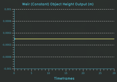
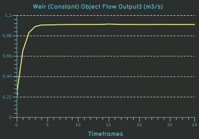
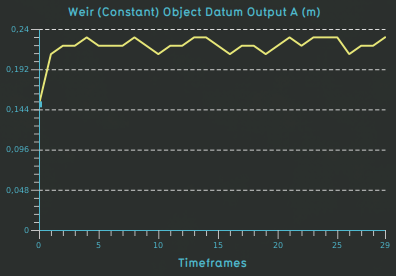
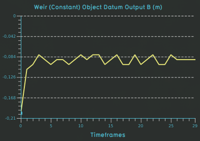
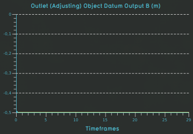
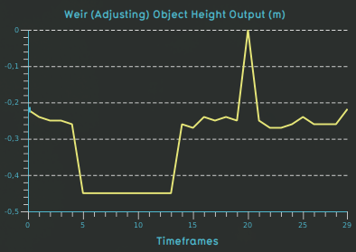
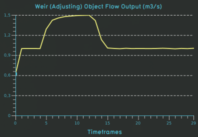
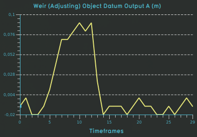
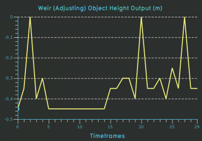
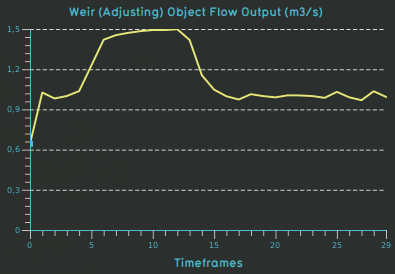
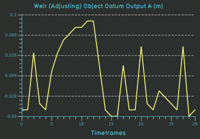
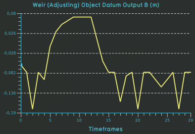
Measured object graphs are displayed below. The following water overlay output attributes are inspected:
- Object height, which is in meters relative to the datum
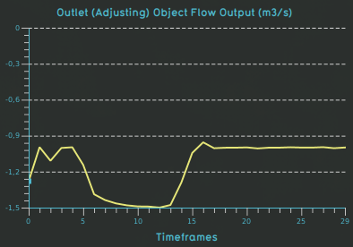
- Object flow, which is in m3/s
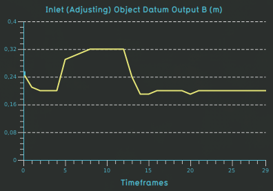
- Object datum a which is in meters relative to the datum
- Object datum b which is in meters relative to the datum
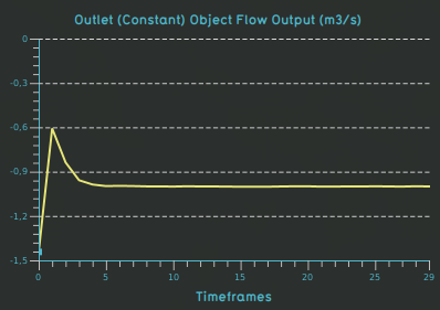
Weir with constant height
- Weir with a constant height:
- Inlet:
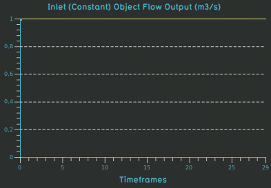
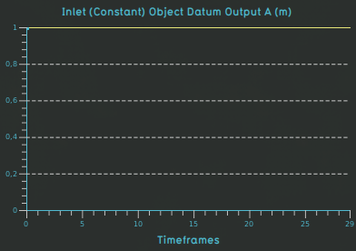
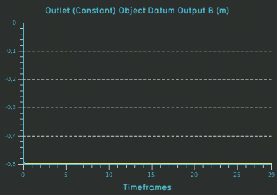
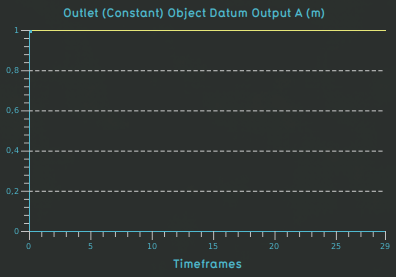
- Outlet:


Weir with manual configured changing height
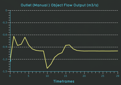
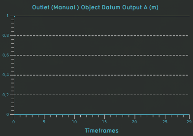
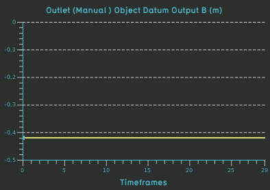
- Weir with a manual configured changing height:
- Inlet:
- Outlet:


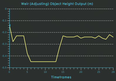
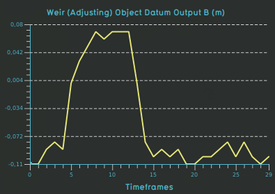
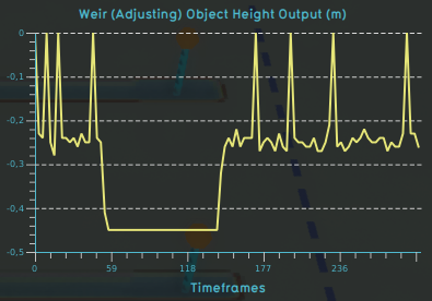
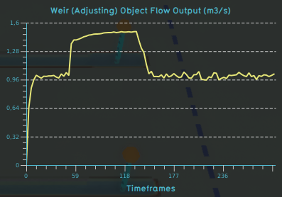
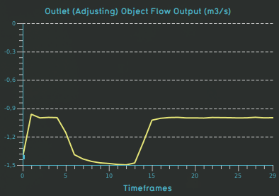
Weir with adjusting height
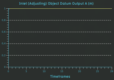
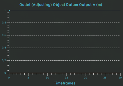
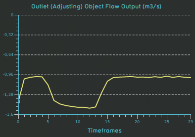
- Weir with an adjusting height:
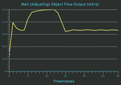
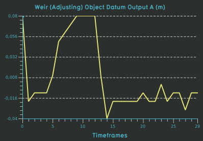
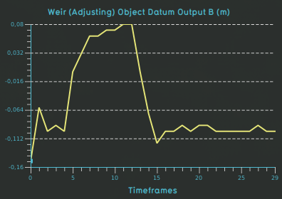
- Inlet:
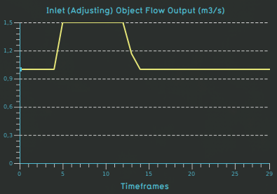
- Outlet:


Variations
Weir adjustment interval
Changing the WEIR_MOVE_INTERVAL_S from 10 seconds to 1 second. This leads to more adjustments. It becomes more apparent with more timeframes (300 in stead of 30).
- Weir with an adjusting height:
- Weir adjusting height with 300 frames:
- Inlet: No changes.
- Outlet:


Weir move step
Changing the WEIR_MOVE_INTERVAL_S from 0.01 meter to 0.05 meter. As you can see, this makes the adjustments more erratic.
- Weir with an adjusting height:
- Inlet: No changes.
- Outlet:


Conclusions
- Weirs can be made to adjust automatically based on changing water levels.
- Be careful when changing the default values of the weir move attributes of the overlay. Do not set the adjustment time too low or the step too high.
How-to's