DXF: Difference between revisions
No edit summary |
|||
| (70 intermediate revisions by 5 users not shown) | |||
| Line 1: | Line 1: | ||
DXF is a file format to exchange CAD data from Autodesk. | DXF{{ref|DXF}} is a file format to exchange CAD data from and to Autodesk's [[AutoCAD]]. DXF is the "open" variant of the "closed" DWG format, which is a proprietary binary format. [[AutoCAD]] can convert these formats to one another generally without loss of data. This file format can be used to import [[Spatial plan|2D spatial plans]]. | ||
==DXF file data== | ==DXF file data== | ||
| Line 8: | Line 8: | ||
* ENTITIES: containing 2 and 3 dimensional shapes | * ENTITIES: containing 2 and 3 dimensional shapes | ||
* BLOCKS: containing 2 and 3 dimension shapes, reusable using INSERTS in ENTITIES. | * BLOCKS: containing 2 and 3 dimension shapes, reusable using INSERTS in ENTITIES. | ||
==Layers== | |||
In the DXF file, entities are always assigned to one particular layer. In AutoCAD, layers can be turned on and off. This visibility does not influence whether or not the entities in this layer can be imported. Layers also have a visualization color, which will be set for blocks and entities belonging to that layer when they do not have a color definition themselves. | |||
==Entities== | ==Entities== | ||
Currently, the following Autodesk CAD | [[File:DXF_shapes.png|thumb|right|200px|A collection of shapes as possible in a DXF file.]] | ||
* LWPOLYLINES (2 dimensional line strings), including bulges.{{ref|LWPOLYLINES}} | Currently, the following Autodesk CAD shape types are supported for entities and blocks: | ||
* LINE (single lines).{{ref|LINE}} | * '''LWPOLYLINES''': (2 dimensional line strings), including bulges.{{ref|LWPOLYLINES}} | ||
* POLYLINE (3 dimensional line strings), currently only interpreted as 2 dimensional. The z-coordinate is ignored.{{ref|POLYLINE}} | * '''LINE''': (single lines).{{ref|LINE}} | ||
* HATCH (polygonal data constructed using other boundary entities).{{ref|HATCH}} | * '''POLYLINE''': (3 dimensional line strings), currently only interpreted as 2 dimensional. The z-coordinate is ignored.{{ref|POLYLINE}} | ||
* CIRCLE: full and partial circles, given a center point, radius and start and end angle.{{ref|CIRCLE}} | * '''HATCH''': (polygonal data constructed using other boundary entities).{{ref|HATCH}} | ||
* ELLIPSE: full and partial ellipses, given a center point, major and minor axis, rotation and start and end angle.{{ref|ELLIPSE}} | * '''CIRCLE''': full and partial circles, given a center point, radius and start and end angle.{{ref|CIRCLE}} | ||
* ARC: curved lines given a center point and a radius.{{ref|ARC}} | * '''ELLIPSE''': full and partial ellipses, given a center point, major and minor axis, rotation and start and end angle.{{ref|ELLIPSE}} | ||
* VERTEX: 2 dimensional point.{{ref|VERTEX}} | * '''ARC''': curved lines given a center point and a radius.{{ref|ARC}} | ||
* POINT: Same as vertex, but 3 dimensional. Currently only interpreted as 2 dimensional. The z-coordinate is ignored.{{ref|POINT}} | * '''VERTEX''': 2 dimensional point.{{ref|VERTEX}} | ||
* SPLINE: 2 dimensional Control point splines are currently supported.{{ref|SPLINE}} Fit point splines are currently not supported. | * '''POINT''': Same as vertex, but 3 dimensional. Currently only interpreted as 2 dimensional. The z-coordinate is ignored.{{ref|POINT}} | ||
* INSERT: Predefined BLOCKS inserted at a point and with a rotation and a scale.{{ref|INSERT}} | * '''SPLINE''': 2 dimensional Control point splines are currently supported.{{ref|SPLINE}} Fit point splines are currently not supported. Splines are converted to a POLYLINE with currently around 10 placed point per processed control point group to approximate the spline. | ||
* '''INSERT''': Predefined '''BLOCKS''' inserted at a point and with a rotation and a scale.{{ref|INSERT}} | |||
Autodesk CAD shape types that are explicitly not yet supported are: | |||
* '''REGION''': Regions are results of an operation (union, difference or intersection) using one or more input shapes. | |||
==Blocks== | ==Blocks== | ||
| Line 29: | Line 36: | ||
BLOCKS can also have attribute defined (ATTDEF) for them. These attributes can contain any string value. | BLOCKS can also have attribute defined (ATTDEF) for them. These attributes can contain any string value. | ||
Each block is converted to one or more unique feature(s). Features within a block are kept separate when they belong to different layers. | Each block is converted to one or more unique feature(s). Features within a block are kept separate when they belong to different layers. For example, a house block can consist of: | ||
== | * A shape for the back garden, in layer ''garden''; | ||
* A shape for the front garden, in layer ''garden''; | |||
* A shape for the garden shed, in layer ''sheds'' or ''housing''; | |||
* A shape or block of the garage, in layer ''garage'' or ''housing''; | |||
* A shape for the parking lane, in layer ''private parking'', ''parking'' or ''pavement'' | |||
* An inserted block for the house itself, in layer ''housing'', where the inserted house block: | |||
** Has a rectangular shape that can be re-scaled for each insert into a parent block and also is in layer ''housing''. | |||
** Has attribute definitions describing for example: | |||
*** the floor height; | |||
*** amount of floors; | |||
*** the slanted roof height; | |||
*** the amount of units in the building, or the unit size; | |||
<gallery widths=300px heights=300px> | |||
File:DXF_block_example.png | |||
File:DXF_block_platform.png|Two blocks imported into a project as a [[measure]]. | |||
</gallery> | |||
==Line stiching== | |||
<gallery>File:DXF_line_overlap.png</gallery> | |||
Not all lines are drawn as closed lines, even though they look closed visually. For example, splines have been encountered that look closed from far away but are actually overlapping. For lines that overlap between start and end point, a line-closing-algorithm will be executed. | |||
{{clear}} | |||
==Lines to Multi-Polygons== | |||
<gallery> | |||
File:DXF_linerings_in_linerings.png | |||
File:DXF_subtracting_shapes.png | |||
</gallery> | |||
Shapes within a layer can be subtracted from each other, without the requirement of hatching the shape. For example, multiple line rings are drawn within each other. By subtracting these correctly, multi-polygons can be created with the expected inside and outside. | Shapes within a layer can be subtracted from each other, without the requirement of hatching the shape. For example, multiple line rings are drawn within each other. By subtracting these correctly, multi-polygons can be created with the expected inside and outside. | ||
{{clear}} | |||
==Colors== | ==Colors== | ||
Colors are stored | Colors can be defined per layer and per entity. Two types of colors are currently supported: | ||
* Indexed colors{{ref|indexcolors}}, where certain integer values represent RGB codes according to a mapping specified for AutoCAD. This color is stored in the feature under the COLOR_INDEX attribute. | |||
* True colors{{ref|truecolors}}, where an integer is used for the concatenated byte (256) numbers for the red, green and blue channel. This color is stored in the feature under the COLOR_TRUE attribute. | |||
Both colors are also converted to a {{software}} [[color]] stored under the COLOR attribute. This attribute can be remapped to a ROOF_COLOR, GEOMETRY_COLOR or any other color to be used directly in a [[Building]]. | |||
{{article end | {{article end | ||
| notes= | | notes= | ||
* | * Due to the generally large number of features, it is advised to use a [[Geo Plugin]] to match [[function]]s to features in the ''Assign Function'' step of the [[Geo Data Wizard]]. This is especially useful when the DXF's layers and blocks use standardized names and attributes, such that you can reuse the GeoPlugin in multiple projects. | ||
| howtos= | | howtos= | ||
* [[How to import a DXF]] | * [[How to import a DXF]] | ||
* [[How to export a DXF reference file for a project]] | |||
* [[How to add terrain changes to a measure from a DXF file]] | |||
* [[How to import AutoCAD BLOCKS with attributes]] | |||
* [[How to predefine the DXF geo-location in AutoCAD]] | |||
* [[How to set the unit of measurement for a DXF]] | |||
* [[How to create a Geo Plugin to import Buildings from a DXF]] | |||
* [[How to deal with a long processing DXF import]] | |||
* [[How to import features with Attributes from DXF]] | |||
* [[How to create a Geo Plugin for DXF files]] | |||
| seealso= | |||
* [[Demo Dxf Import Project]] | |||
* [[DXF requirements]] | |||
| references=<references> | | references=<references> | ||
{{ref|DXF | |||
|name=DXF | |||
|author= | |||
|page= | |||
|source= | |||
|link=https://help.autodesk.com/view/ACD/2023/ENU/?guid=GUID-D4242737-58BB-47A5-9B0E-1E3DE7E7D647 | |||
|lastvisit=28-11-2022 | |||
}} | |||
{{ref|LWPOLYLINES | {{ref|LWPOLYLINES | ||
|name=LWPOLYLINES | |name=LWPOLYLINES | ||
| Line 142: | Line 196: | ||
|lastvisit=26-9-2022 | |lastvisit=26-9-2022 | ||
}} | }} | ||
{{ref|indexcolors | |||
{{ref| | |||
|name=AutoCAD Color Index (ACI) RGB equivalents | |name=AutoCAD Color Index (ACI) RGB equivalents | ||
|author= | |author= | ||
| Line 150: | Line 203: | ||
|link=https://gohtx.com/acadcolors.php | |link=https://gohtx.com/acadcolors.php | ||
|lastvisit=26-9-2022 | |lastvisit=26-9-2022 | ||
}} | |||
{{ref|truecolors | |||
|name=AutoCAD True Color | |||
|author= | |||
|page= | |||
|source= | |||
|link=https://knowledge.autodesk.com/support/autocad/learn-explore/caas/CloudHelp/cloudhelp/2023/ENU/AutoCAD-Core/files/GUID-BE316D65-8824-4114-8D7D-D02AE8BDAB70-htm.html | |||
|lastvisit=28-11-2022 | |||
}} | }} | ||
</references> | </references> | ||
| Line 155: | Line 216: | ||
{{GeoDataOverview}} | {{GeoDataOverview}} | ||
[[Category:DXF]] | |||
Latest revision as of 14:56, 8 October 2025
DXF[1] is a file format to exchange CAD data from and to Autodesk's AutoCAD. DXF is the "open" variant of the "closed" DWG format, which is a proprietary binary format. AutoCAD can convert these formats to one another generally without loss of data. This file format can be used to import 2D spatial plans.
DXF file data
A DXF file is subdivided in several sections. The sections in this file that we inspect are:
- HEADER: contains location and scaling information
- GEODATA: contains geo-location information
- TABLES: containing definitions of layers
- ENTITIES: containing 2 and 3 dimensional shapes
- BLOCKS: containing 2 and 3 dimension shapes, reusable using INSERTS in ENTITIES.
Layers
In the DXF file, entities are always assigned to one particular layer. In AutoCAD, layers can be turned on and off. This visibility does not influence whether or not the entities in this layer can be imported. Layers also have a visualization color, which will be set for blocks and entities belonging to that layer when they do not have a color definition themselves.
Entities
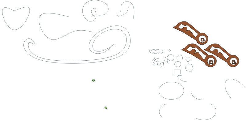
Currently, the following Autodesk CAD shape types are supported for entities and blocks:
- LWPOLYLINES: (2 dimensional line strings), including bulges.[2]
- LINE: (single lines).[3]
- POLYLINE: (3 dimensional line strings), currently only interpreted as 2 dimensional. The z-coordinate is ignored.[4]
- HATCH: (polygonal data constructed using other boundary entities).[5]
- CIRCLE: full and partial circles, given a center point, radius and start and end angle.[6]
- ELLIPSE: full and partial ellipses, given a center point, major and minor axis, rotation and start and end angle.[7]
- ARC: curved lines given a center point and a radius.[8]
- VERTEX: 2 dimensional point.[9]
- POINT: Same as vertex, but 3 dimensional. Currently only interpreted as 2 dimensional. The z-coordinate is ignored.[10]
- SPLINE: 2 dimensional Control point splines are currently supported.[11] Fit point splines are currently not supported. Splines are converted to a POLYLINE with currently around 10 placed point per processed control point group to approximate the spline.
- INSERT: Predefined BLOCKS inserted at a point and with a rotation and a scale.[12]
Autodesk CAD shape types that are explicitly not yet supported are:
- REGION: Regions are results of an operation (union, difference or intersection) using one or more input shapes.
Blocks
Blocks (BLOCKS) are parts in a CAD drawing that can be reused multiple times by inserting them at different locations with optional alternative rotations and scales. The usage of blocks in a DXF is supported.[13]
Blocks can consist of shapes similar as to those definable in entities, including the insertion (INSERT) of other blocks. Each of these shapes can belong to a different layer. BLOCKS can also have attribute defined (ATTDEF) for them. These attributes can contain any string value.
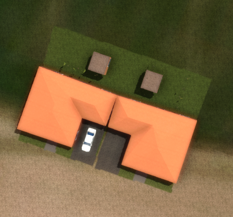
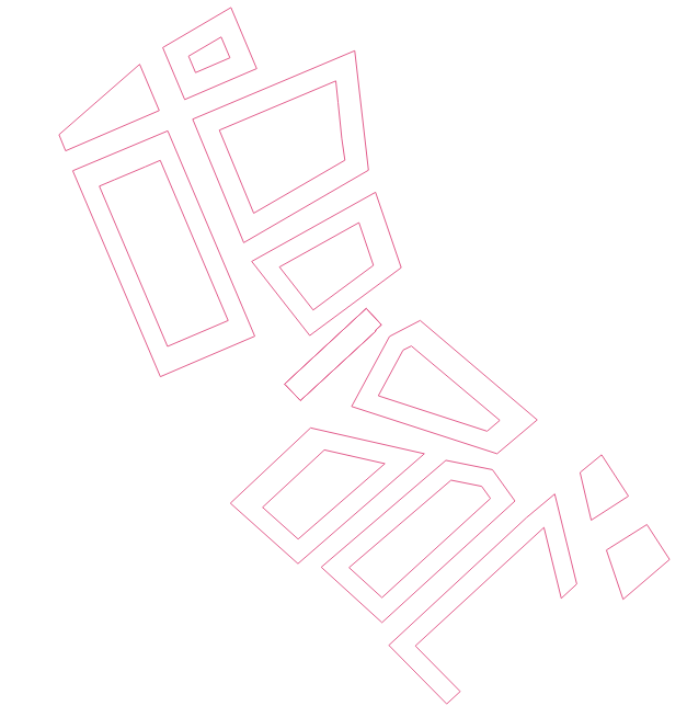
Each block is converted to one or more unique feature(s). Features within a block are kept separate when they belong to different layers. For example, a house block can consist of:
- A shape for the back garden, in layer garden;
- A shape for the front garden, in layer garden;
- A shape for the garden shed, in layer sheds or housing;
- A shape or block of the garage, in layer garage or housing;
- A shape for the parking lane, in layer private parking, parking or pavement
- An inserted block for the house itself, in layer housing, where the inserted house block:
- Has a rectangular shape that can be re-scaled for each insert into a parent block and also is in layer housing.
- Has attribute definitions describing for example:
- the floor height;
- amount of floors;
- the slanted roof height;
- the amount of units in the building, or the unit size;
-
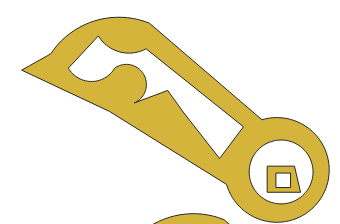
Two blocks imported into a project as a measure.
Line stiching
Not all lines are drawn as closed lines, even though they look closed visually. For example, splines have been encountered that look closed from far away but are actually overlapping. For lines that overlap between start and end point, a line-closing-algorithm will be executed.
Lines to Multi-Polygons
Shapes within a layer can be subtracted from each other, without the requirement of hatching the shape. For example, multiple line rings are drawn within each other. By subtracting these correctly, multi-polygons can be created with the expected inside and outside.
Colors
Colors can be defined per layer and per entity. Two types of colors are currently supported:
- Indexed colors[14], where certain integer values represent RGB codes according to a mapping specified for AutoCAD. This color is stored in the feature under the COLOR_INDEX attribute.
- True colors[15], where an integer is used for the concatenated byte (256) numbers for the red, green and blue channel. This color is stored in the feature under the COLOR_TRUE attribute.
Both colors are also converted to a Tygron Platform color stored under the COLOR attribute. This attribute can be remapped to a ROOF_COLOR, GEOMETRY_COLOR or any other color to be used directly in a Building.
Notes
- Due to the generally large number of features, it is advised to use a Geo Plugin to match functions to features in the Assign Function step of the Geo Data Wizard. This is especially useful when the DXF's layers and blocks use standardized names and attributes, such that you can reuse the GeoPlugin in multiple projects.
How-to's
- How to import a DXF
- How to export a DXF reference file for a project
- How to add terrain changes to a measure from a DXF file
- How to import AutoCAD BLOCKS with attributes
- How to predefine the DXF geo-location in AutoCAD
- How to set the unit of measurement for a DXF
- How to create a Geo Plugin to import Buildings from a DXF
- How to deal with a long processing DXF import
- How to import features with Attributes from DXF
- How to create a Geo Plugin for DXF files
See also
References
- ↑ DXF ∙ Found at: https://help.autodesk.com/view/ACD/2023/ENU/?guid=GUID-D4242737-58BB-47A5-9B0E-1E3DE7E7D647 ∙ (last visited: 28-11-2022)
- ↑ LWPOLYLINES ∙ Found at: https://knowledge.autodesk.com/support/autocad/learn-explore/caas/CloudHelp/cloudhelp/2022/ENU/AutoCAD-Core/files/GUID-392BF13C-D9E7-47A8-8E07-435296332279-htm.html ∙ (last visited: 26-9-2022)
- ↑ LINE ∙ Found at: https://knowledge.autodesk.com/support/autocad/learn-explore/caas/CloudHelp/cloudhelp/2022/ENU/AutoCAD-Core/files/GUID-DB0FA734-8F5C-4000-92FF-89BA2D42CA21-htm.html ∙ (last visited: 26-9-2022)
- ↑ POLYLINE ∙ Found at: https://knowledge.autodesk.com/support/autocad/learn-explore/caas/CloudHelp/cloudhelp/2022/ENU/AutoCAD-Core/files/GUID-392BF13C-D9E7-47A8-8E07-435296332279-htm.html ∙ (last visited: 26-9-2022)
- ↑ HATCH ∙ Found at: https://knowledge.autodesk.com/support/autocad/learn-explore/caas/CloudHelp/cloudhelp/2023/ENU/AutoCAD-Core/files/GUID-27C104F2-B687-4025-B50B-A58E37329832-htm.html?us_oa=akn-us&us_si=8126699c-9f97-4fa3-9b23-fa556e058edb&us_st=Hatch ∙ (last visited: 26-9-2022)
- ↑ CIRCLE ∙ Found at: https://knowledge.autodesk.com/support/autocad/learn-explore/caas/CloudHelp/cloudhelp/2022/ENU/AutoCAD-Core/files/GUID-EDC69C38-6651-46DA-AFCC-56F2EB0A6AC6-htm.html ∙ (last visited: 26-9-2022)
- ↑ ELLIPSE ∙ Found at: https://knowledge.autodesk.com/support/autocad/learn-explore/caas/CloudHelp/cloudhelp/2022/ENU/AutoCAD-Core/files/GUID-2461D382-B7E5-44B3-A34C-735CE0089C8D-htm.html ∙ (last visited: 26-9-2022)
- ↑ ARC ∙ Found at: https://knowledge.autodesk.com/support/autocad/learn-explore/caas/CloudHelp/cloudhelp/2022/ENU/AutoCAD-Core/files/GUID-C78378FD-4704-4D0A-9D86-82FCBB118097-htm.html ∙ (last visited: 26-9-2022)
- ↑ VERTEX ∙ Found at: https://knowledge.autodesk.com/support/autocad/learn-explore/caas/CloudHelp/cloudhelp/2023/ENU/AutoCAD-Core/files/GUID-84591B48-71B9-4258-B287-CD2391C946D2-htm.html ∙ (last visited: 26-9-2022)
- ↑ POINT ∙ Found at: https://knowledge.autodesk.com/support/autocad/learn-explore/caas/CloudHelp/cloudhelp/2023/ENU/AutoCAD-Core/files/GUID-3F5861A1-9A63-42A6-8F12-3395771BAA6D-htm.html?us_oa=akn-us&us_si=cd548ae9-dde6-4a75-bb71-c74923034ef2&us_st=Point ∙ (last visited: 26-9-2022)
- ↑ SPLINE ∙ Found at: https://knowledge.autodesk.com/support/autocad/learn-explore/caas/CloudHelp/cloudhelp/2023/ENU/AutoCAD-Core/files/GUID-58316136-30EB-499C-ACAD-31D0C653B2B2-htm.html ∙ (last visited: 26-9-2022)
- ↑ INSERT ∙ Found at: https://knowledge.autodesk.com/support/autocad/learn-explore/caas/CloudHelp/cloudhelp/2023/ENU/AutoCAD-Core/files/GUID-BC0FD3C1-3BFC-4C5D-AB9A-BF480D5084BE-htm.html ∙ (last visited: 26-9-2022)
- ↑ BLOCKS ∙ Found at: https://knowledge.autodesk.com/support/autocad/learn-explore/caas/CloudHelp/cloudhelp/2023/ENU/AutoCAD-Core/files/GUID-7410E7FB-3E0D-4411-B8F6-DBD59C71E87D-htm.html ∙ (last visited: 26-9-2022)
- ↑ AutoCAD Color Index (ACI) RGB equivalents ∙ Found at: https://gohtx.com/acadcolors.php ∙ (last visited: 26-9-2022)
- ↑ AutoCAD True Color ∙ Found at: https://knowledge.autodesk.com/support/autocad/learn-explore/caas/CloudHelp/cloudhelp/2023/ENU/AutoCAD-Core/files/GUID-BE316D65-8824-4114-8D7D-D02AE8BDAB70-htm.html ∙ (last visited: 28-11-2022)
